
TM 5-3805-255-14
0050
INSTALLATION
00050
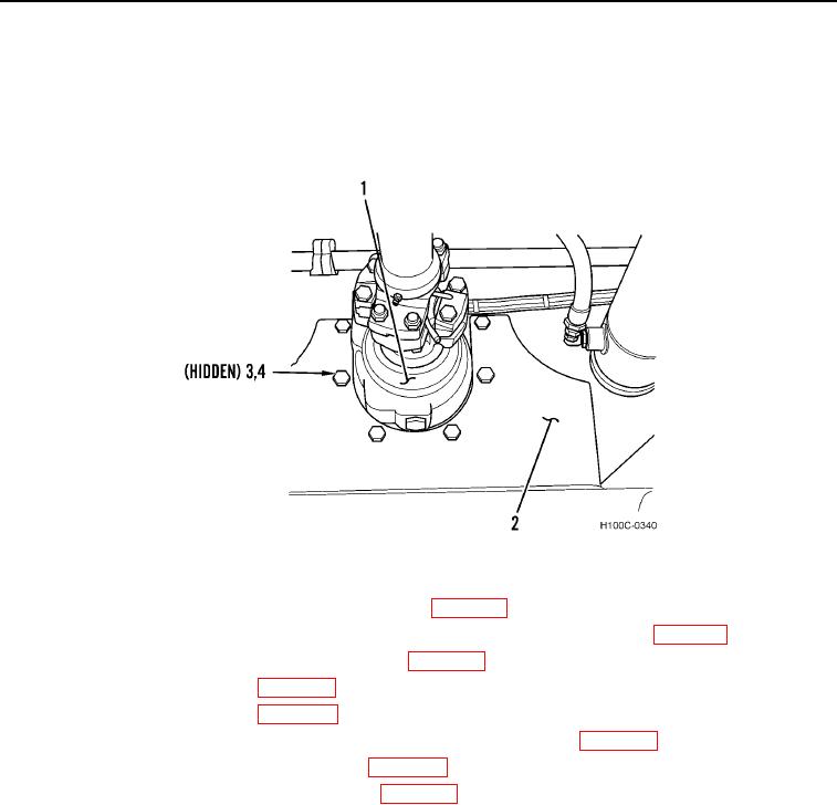
1. Install transfer drive (Figure 18, Item 1) in loader frame crossmember (Figure 18, Item 2).
2. Install six new lockwashers (Figure 18, Item 4) and capscrews (Figure 18, Item 3) through crossmember
(Figure 18, Item 2) and into transfer drive housing (Figure 18, Item 1). Tighten capscrews to 80 to 90 lb-ft
(108 to 122 Nm).
Figure 18. Transfer Drive Installation.
0050
3. Install transfer drive-to-front differential propeller shaft (WP 0049).
4. Fill transfer drive housing to full mark on dipstick with 1 pt (0.473 L) of gear lubricant (WP 0018).
5. Install transmission-to-transfer drive propeller shaft (WP 0049).
6. Install parking brake assembly (WP 0058).
7. Connect parking brake linkage (WP 0057).
8. Remove safety pins from lockbar and reposition lockbar in stowed position (WP 0005).
9. Turn battery disconnect switch to ON position (WP 0004).
10. Start engine and check transfer drive operation (WP 0005).
END OF TASK
END OF WORK PACKAGE
0050-14