
TM 5-3805-255-14
0060
REMOVAL
00060
WARNING
Chock wheels to prevent loader from moving. Failure to follow this warning may result in
injury or death to personnel and damage to equipment.
CAUTION
Cap air and hydraulic tubes to prevent contamination. Failure to follow this caution may
result in damage to equipment.
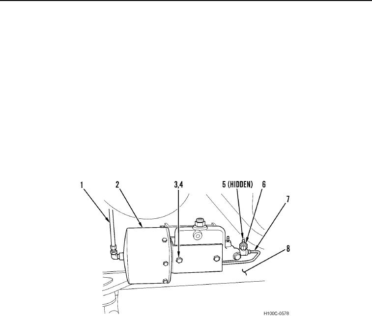
1. Disconnect air tube (Figure 1, Item 1) and hydraulic tube (Figure 1, Item 7) from power cluster (Figure 1,
Item 2).
2. Remove two nuts (Figure 1, Item 3), lockwashers (Figure 1, Item 4), and power cluster (Figure 1, Item 2) from
frame (Figure 1, Item 8). Discard lockwashers.
3. If left power cluster (Figure 1, Item 2) is being removed, remove stop light switch wires (Figure 1, Item 5) from
stop light switch (Figure 1, Item 6).
Figure 1. Power Cluster Lines.
060
END OF TASK
0060-2