
TM 5-3805-255-14
0060
DISASSEMBLY CONTINUED
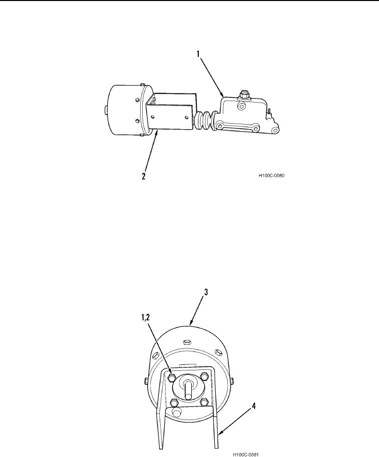
3. Remove hydraulic cylinder (Figure 3, Item 1) from bracket (Figure 3, Item 2).
Figure 3. Hydraulic Cylinder.
060
NOTE
Late model units are equipped with an indicator rod which is installed in place of the lower
right-hand bolt. Also, an external breather replaces the filter screen just below the lower
left-hand bolt.
4. Remove four bolts (Figure 4, Item 1), lockwashers (Figure 4, Item 2), and bracket (Figure 4, Item 4) from air
cylinder (Figure 4, Item 3). Discard lockwashers.
Figure 4. Bracket.
060
0060-4