
TM 5-3805-255-14
0059
INSTALLATION
00059
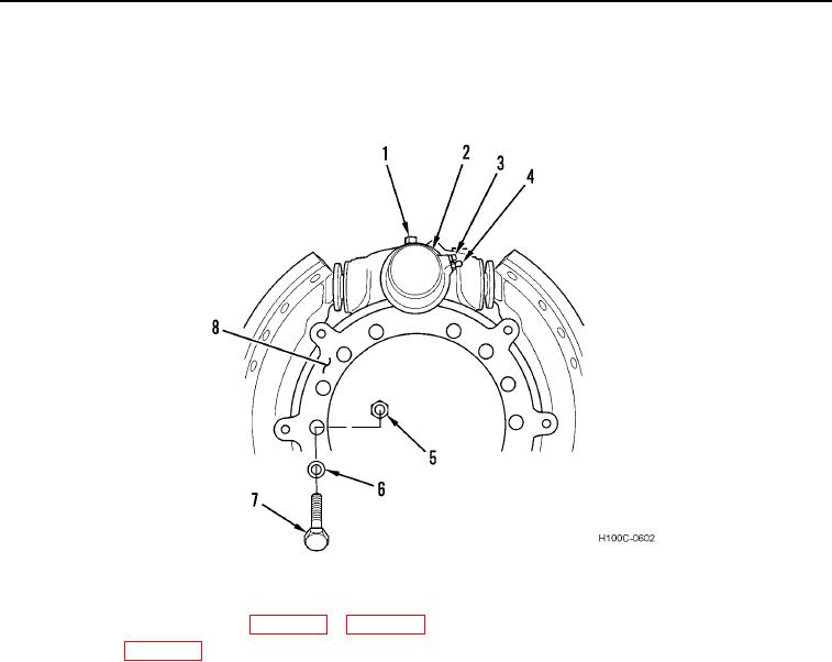
1. Install spider (Figure 21, Item 8), 15 washers (Figure 21, Item 6), bolts (Figure 21, Item 7), and new locknuts
(Figure 21, Item 5) on axle.
Figure 21. Spider Assembly.
0059
3. Install wheel (WP 0066).
4. Adjust brake lining to drum clearance.
5. Bleed hydraulic brake circuit. See Bleeding Hydraulic Brake Circuit in this work package.
END OF TASK
ADJUSTMENT
00059
WARNING
Align frame halves and install safety bar with wheels in straight-ahead position. Failure to
follow this warning may result in serious injury or death to personnel.
1. Use a suitable lifting device to raise loader until wheel is clear of ground. Use a suitable supporting device to
support loader.
2. While rotating wheel, rotate star wheel until brake lining drags on drum or rotate star wheel in opposite direc-
tion until drag is relieved.
3. Lift loader, remove supporting device, lower loader to ground. Remove lifting device.
END OF TASK
0059-19