
TM 5-3805-255-14
0080
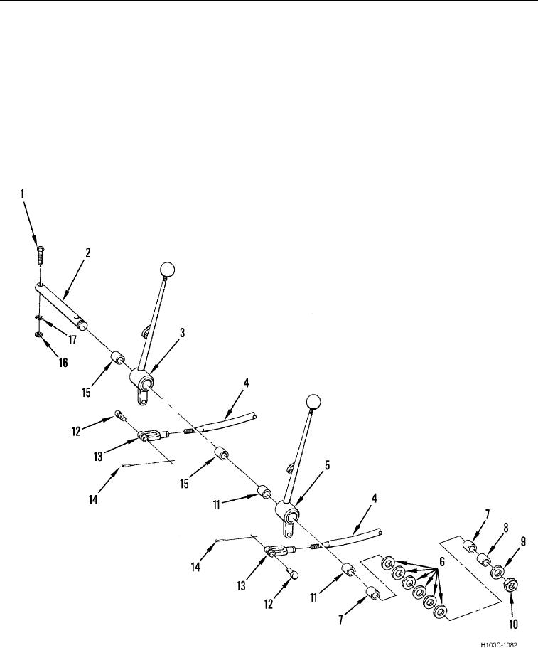
DISASSEMBLY CONTINUED
4. Remove two cotter pins (Figure 4, Item 14) from clevis pins (Figure 4, Item 12). Discard cotter pins.
5. Remove two clevis pins (Figure 4, Item 12) and cable ends (Figure 4, Item 13) from control levers (Figure 4,
Items 3 and 5).
6. Remove nut (Figure 4, Item 10), flat washer (Figure 4, Item 9), and six spacer washers (Figure 4, Item 6) from
control lever pin (Figure 4, Item 2).
7. Remove nut (Figure 4, Item 16), lockwasher (Figure 4, Item 17), and bolt (Figure 4, Item 1) from each end of
control lever pin (Figure 4, Item 2). Discard lockwasher.
8. Remove control lever pin (Figure 4, Item 2), two control levers (Figure 4, Items 3 and 5), and seven bushings
(Figure 4, Items 7, 8, 11, and 15) from mounting brackets.
Figure 4. Control Levers.
0080
END OF TASK
0080-5