
TM 5-3805-255-14
0080
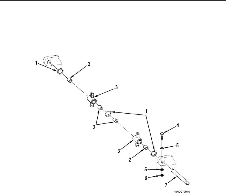
DISASSEMBLY
00080
1. Remove nut (Figure 3 , Item 6), two washers (Figure 3 , Item 5), and bolt (Figure 3 , Item 4) from bellcrank
lever pin (Figure 3 , Item 7).
2. Remove bellcrank lever pin (Figure 3 , Item 7), three O-rings (Figure 3 , Item 1), and two bellcrank levers
(Figure 3 , Item 3) from frame mounting brackets. Discard O-rings.
3. Remove four bushings (Figure 3 , Item 2) from two bellcrank levers (Figure 3 , Item 3).
H100C-0879
Figure 3. Bellcrank Assembly.
0080
0080-4