• Home
  • Download PDF
  • Order CD-ROM
  • Order in Print
Figure 1. Hydraulic Control Linkage at Bellcrank.
Figure 3. Bellcrank Assembly.

Maintenance Manual For Loader, Scoop Type, Ded 4 X 4, Articulated Frame Steer, 4.5 To 5 Cu. Yd.
Page Navigation
  712    713    714    715    716  717  718    719    720    721    722  
img
TM 5-3805-255-14
0080
REMOVAL CONTINUED
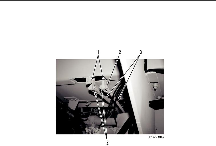
5. Remove two cotter pins (Figure 2, Item 4) from clevis pins (Figure 2, Item 2). Discard cotter pins.
6. Remove two clevis pins (Figure 2, Item 2) and control rods (Figure 2, Item 3) from control levers (Figure 2,
Item 1).
7. Remove two control rods (Figure 2, Item 3) from loader.
Figure 2. Control Rods to Control Levers.
0080
END OF TASK
0080-3


Privacy Statement
Press Release
Contact

© Copyright Integrated Publishing, Inc.. All Rights Reserved.