
TM 5-3805-255-14
0080
INSTALLATION CONTINUED
NOTE
Welded ends of control rods go to bellcrank. Be sure control lever end of rods have bend
angling down from clevis pins.
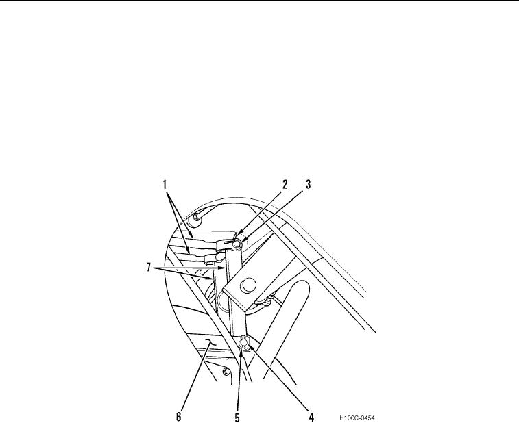
3. Install two control rods (Figure 8, Item 1) and clevis pins (Figure 8, Item 3) on bellcrank (Figure 8, Item 7).
4. Install two new cotter pins (Figure 8, Item 2) in clevis pins (Figure 8, Item 3).
5. Install two clevis pins (Figure 8, Item 4) and linkage (Figure 8, Item 6) on bellcrank (Figure 8, Item 7).
6. Install two new cotter pins (Figure 8, Item 5) in clevis pins (Figure 8, Item 4).
Figure 8. Hydraulic Control Linkage at Bellcrank.
0080
END OF TASK
0080-10