• Home
  • Download PDF
  • Order CD-ROM
  • Order in Print
Figure 6. Bellcrank Assembly.
Figure 8. Hydraulic Control Linkage at Bellcrank.

Maintenance Manual For Loader, Scoop Type, Ded 4 X 4, Articulated Frame Steer, 4.5 To 5 Cu. Yd.
Page Navigation
  718    719    720    721    722  723  724    725    726    727    728  
img
TM 5-3805-255-14
0080
INSTALLATION
00080
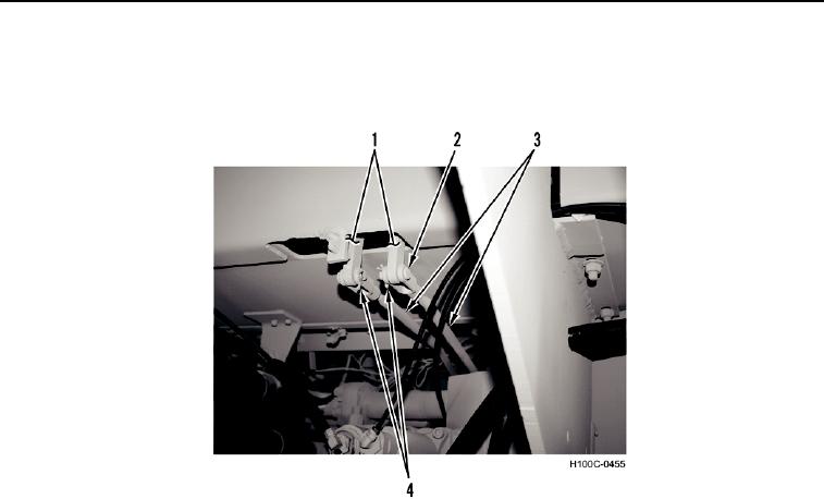
1. Install two control rods (Figure 7, Item 3) and clevis pins (Figure 7, Item 2) on control levers (Figure 7, Item 1).
2. Install two new cotter pins (Figure 7, Item 4) in clevis pins (Figure 7, Item 2).
Figure 7. Control Rods.
0080
0080-9


Privacy Statement
Press Release
Contact

© Copyright Integrated Publishing, Inc.. All Rights Reserved.