TM 5-3805-255-14
0087
CYLINDER SLEEVES INSTALLATION CONTINUED
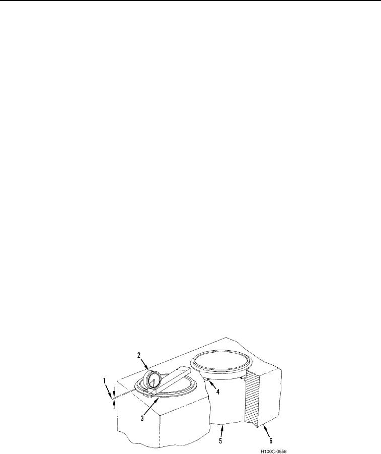
6. Use a dial indicator (Figure 9, Item 2) to determine cylinder sleeve (Figure 9, Items 1 and 4) protruded height.
as follows:
a. Place dial indicator, with block, across cylinder sleeve flange (Figure 9, Item 3). Top of sleeve must be
clean and free of carbon.
b. With dial indicator pointer on cylinder sleeve flange, set dial indicator pointer at zero. Move indicator block
until pointer drops to crankcase deck (Figure 9, Item 6) and take a micrometer reading.
c.
If cylinder sleeve flange is below crankcase deck, rest indicator pointer on crankcase deck and set
indicator at zero. Move indicator block until pointer drops to sleeve flange and take reading.
d. This check must be made at four points around cylinder and average reading used to determine which
shim (Figure 9, Item 4) is needed.
CAUTION
If a variation greater than 0.002 in. (0.05 mm) exists between these readings, sleeve must
be removed and crankcase counterbore depth checked at several points around
counterbore using depth gauge, 1 020 560 R91. See Crankcase Counterbore Refacing in
this work package.
Maximum variation between points of measurement cannot exceed 0.002 in. (0.05 mm).
Mark each sleeve before removing so that it can be reinstalled in same position as it was
while making protrusion check.
If engine has been run with a blown gasket ring or evidence of water leakage is present,
check all sleeve counterbores to determine if resurfacing is necessary prior to installing
shims.
Shims are available in the following thicknesses: 0.002 in. (0.05 mm), 0.004 in. (0.1016
mm), 0.010 in. (0.254 mm), 0.020 in. (0.508 mm), and 0.032 in. (0.8128 mm).
This must be done even if sleeve protrusion checked out to be within 0.002 in. (0.05 mm)
specification.
Make sure that sleeve counterbore and sleeve flange are clean and free of foreign
material.
Failure to follow these instructions may result in damage to equipment.
Figure 9. Cross-Section of Engine Crankcase.
0087
0087-10

