TM 5-3805-255-14
0087
CLEANING, INSPECTION, AND REPAIR CONTINUED
00087
Wear Sleeve Insert (Lower) Installation
00087
NOTE
When erosion of crankcase at lower cylinder sleeve sealing area takes place, lower bore
must be machined and an insert installed.
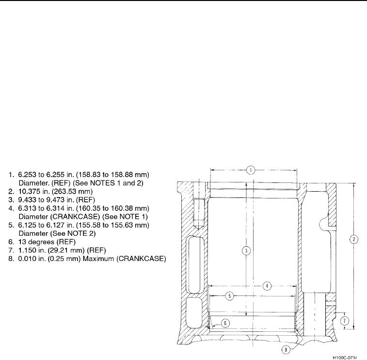
1. Refer to Figure 5 for rework dimensions for crankcase. Surface finish to be 125 micro-in. (3.18 micrometers).
2. Apply Loctite 638 Retaining Compound to crankcase and install sleeve with chamfer on outside diameter
towards bottom and chamfer on inside diameter towards top.
3. Remove any excess retaining compound.
Wear Sleeve Insert (Upper) Installation
00087
Level crankcase so that machine spindle is perpendicular to crankcase top deck. Locate spindle at center of crank-
case lower pilot bore and machine new counterbore for insert as specified in Figure 5.
Figure 5. Rework for Crankcase Lower Sleeve Insert.
0087
(1) Bores (Figure 5, Items 1 and 4) must be concentric within 0.001 in. (0.03 mm) total indicator reading.
(2) Bores (Figure 6, Items 1 and 5) must be concentric within 0.002 in. (0.05 mm) total indicator reading
and their center lines must be square with crankshaft bearing bores within 0.003 in. (0.08 mm) in 12 in.
(305 mm).
(3) Care must be taken to hold counterbore seat parallel with top deck as specified. Failure to follow these
instructions may result in damage to equipment.
0087-6

