
TM 5-3805-255-14
0087
CYLINDER SLEEVES INSTALLATION CONTINUED
NOTE
Each cylinder may be adjusted independently. It is acceptable to use shims of one
thickness in one cylinder, and shims of another thickness in a different cylinder to arrive at
correct total cylinder sleeve height for proper combustion seating.
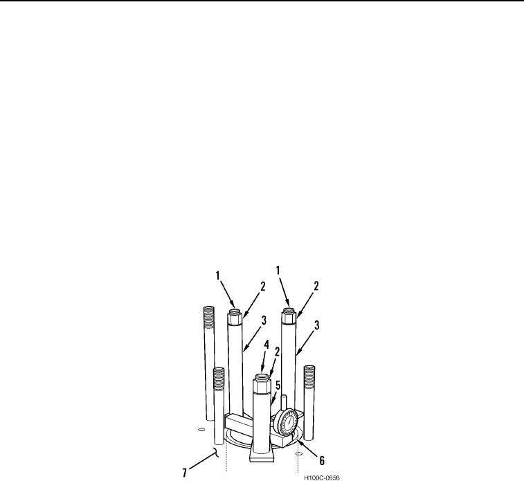
3. Install cylinder sleeve (Figure 8, Item 6), without O-rings, into crankcase (Figure 8, Item 7). Clamp sleeve down
by placing a sleeve holding adapter over three cylinder studs (Figure 8, Items 1 and 4).
NOTE
All pipes must be square and flat on both sides.
4. Place three pipes (Figure 8, Items 3 and 5) with a maximum ID of 1.00 in. (25 mm) over same three studs
(Figure 8, Items 1 and 4). For long studs (Figure 8, Item 1) use 8.500 in. (215 mm) long pipe (Figure 8, Item 3)
and 4.500 in. (115 mm) pipe for short stud.
5. Place regular cylinder head nuts (Figure 8, Item 2) on three studs (Figure 8, Items 1 and 4). Torque nuts
(Figure 8, Item 2) to 150 lb-ft in three stages of 50 lb-ft (68 Nm), 100 lb-ft (135 Nm) and 150 lb-ft (155 Nm).
Figure 8. Cylinder Sleeve Clamping.
0087
0087-9