TM 5-3805-255-14
0087
CLEANING, INSPECTION, AND REPAIR CONTINUED
00087
6. Machine top of insert to be flush to 0.002 in. (0.051 mm) above crankcase top deck without removing any metal
from crankcase top deck.
7. Record cylinder sleeve protrusion measurements from crankcase top deck and not insert. The amount of clear-
ance between deck of crankcase and top surface of sleeve flange must not exceed 0.002 to 0.004 in. (0.050 to
0.100 mm).
END OF TASK
CYLINDER SLEEVES INSTALLATION
00087
CAUTION
Whenever cylinder heads are removed, new head gaskets must be used. The pressure
contact surfaces of integral gasket rings are grooved to provide a better seal. This surface
flattens out when heads are torqued and may destroy sealing effect if reused. Check
cylinder sleeve flange protrusion as described in this procedure. After sleeve flange
protrusion has been determined, adjust cylinder to obtain correct total height (shims)
required for proper combustion sealing. Failure to follow these instructions may result in
damage to equipment.
When shimming of sleeve is necessary to obtain proper protrusion, it is best to use no
more than two shims, and only one if possible, per sleeve. If more shims are used, they
may set or extrude from their position. If necessary, resurface counterbore and use a
thicker shim rather than using more shims of a smaller size. The total thickness of all
shims used per sleeve cannot exceed 0.064 in. (1.63 mm). Failure to follow these
instructions may result in damage to equipment.
1. Follow instructions that pertain to existing condition of your engine.
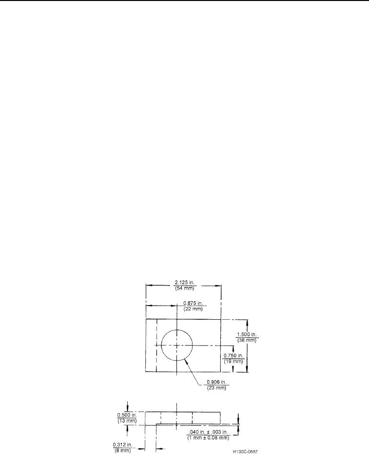
2. Construct Cylinder Sleeve Holding Adapter using locally obtained materials as shown in Figure 7.
Figure 7. Cylinder Sleeve Holding Adapter.
0087
0087-8

