
TM 5-3805-255-14
0095
VALVE RECONDITIONING CONTINUED
Valve Guides
00095
WARNING
Solvent cleaning compound MIL-PRF-680 Type III is an environmentally complaint and
low-toxicity material. However, it may be irritating to the eyes and skin. Use protective
gloves and goggles. Use in well-ventilated areas. Keep away from open flames and other
sources of ignition. Failure to do so may result in injury or death to personnel.
NOTE
Guides require very careful cleaning. Carbon left in guide will deflect pilot and result in
inaccurate reconditioning of valve seat.
1. Use a 7/16 in. (11 mm) nylon bristle brush, solvent, and power drill to remove residue in guide bore. Guides
must be washed down with a strong soap solution. As an option use a 3/8 in. (10 mm) spiral brush for cleaning.
Examine bore for signs of burning, blistering, cracking, and excessive wear.
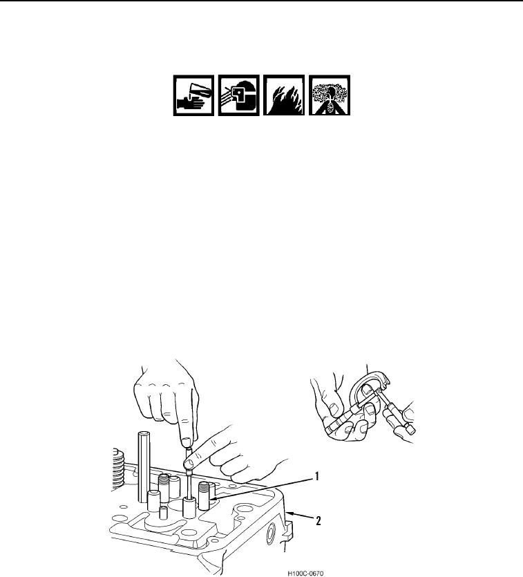
2. Measure ID of valve guide (Figure 11, Item 1) with a small hole gauge at several points around its circumfer-
ence and along its length. If readings are above maximum permissible dimensions, replace guide (see Intake
and Exhaust Valve Specifications in this work package.
3. Press out worn guides from underside of cylinder head (Figure 11, Item 2) from valve port up through top. Use
a mandrel slightly smaller than guide in order to prevent jamming.
Figure 11. Checking Guide ID.
0095
0095-9