
TM 5-3805-255-14
0095
VALVE RECONDITIONING CONTINUED
4. Avoid taking heavy grinding cuts as this heats valve head excessively, produces an unsatisfactory valve face,
and necessitates dressing grinding wheel frequently. Repeated light grinding cuts are preferred until a true
face of even width is obtained around valve. Avoid passing stone beyond face of valve, as this will cause ridg-
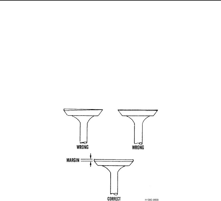
ing and grooving of stone surface and make dressing of stone necessary. Replace valves with distorted heads,
which produce an uneven face, and valves which grind down to thin edge (Figure 9).
5. Maximum amount of material which can be removed from either valve seat or valve face is:
a. 0.01 in. (0.25 mm) for exhaust.
b. 0.012 in. (0.30 mm) for intake.
c.
0.015 in. (0.38 mm) is combined maximum material removed for valve face and seat.
6. Only minimum amount needed to make a good valve seat contact should be removed. If necessary to remove
more than maximums stated above, valves and/or valve seat inserts must be replaced.
7. At times, large amounts of heat scale may be found on exhaust valves. This is rough on grinding stone. Fre-
quent redressing of stone will be necessary to maintain a smooth, even surface, and a uniform set of face
angles.
Figure 9. Maintaining Proper Margin.
0095
0095-7