
TM 5-3805-255-14
0097
INSTALLATION
00097
1. If crankcase front plate was removed, install as follows:
a. Install a new gasket to front on crankcase and install front plate with hydraulic pump attached (if equipped).
Install front plate bolts and locks. Tighten bolts securely.
b. If equipped with hydraulic pump, connect oil line manifold to pump.
c.
Install adapter housing with injection pump attached (WP 0100). Connect all lines to injection pump.
d. Install lubricating oil and water pump assembly (WP 0023).
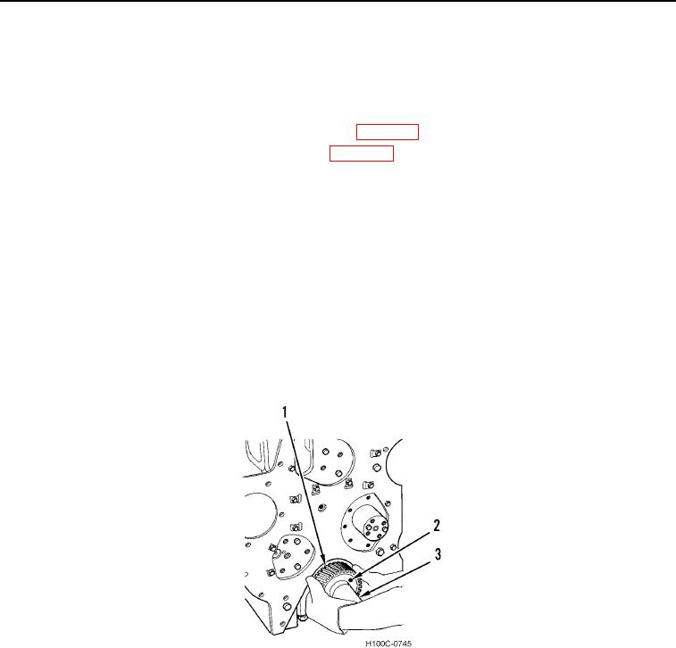
2. Install crankshaft gear key in keyway in crankshaft. Heat crankshaft drive gear (Figure 121) to 475F (245C).
WARNING
Use suitable heat-resistant gloves to handle heated crankshaft drive gear. Failure to follow
this caution will result in injury to personnel.
CAUTION
Be sure crankshaft drive gear is aligned on crankshaft. Failure to follow this caution will
result in damage to engine.
3. Position crankshaft drive gear (Figure 12, Item 1) on crankshaft (Figure 12, Item 3) with timing mark (Figure 12,
Item 2) facing out. Drive gear onto crankshaft until it bottoms.
Figure 12. Installing Crankshaft Gear.
0097
0097-12