TM 5-3805-255-14
0097
INSTALLATION CONTINUED
WARNING
Use extreme caution when lifting heavy parts. Provide adequate support and use
assistance during procedure. Ensure that lifting equipment used is on solid footing, is in good
condition, and is of suitable lift capacity. Keep clear of heavy parts supported only by lifting
equipment. Failure to follow this warning may result in death or injury to personnel or damage to
equipment.
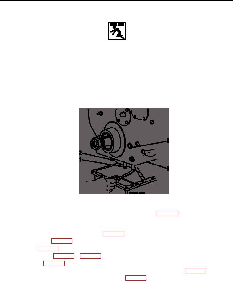
17. Install front cover (Figure 19, Item 3), bolts (Figure 19, Item 4), and locks. Be sure to install two bolts and locks
located in fan drive housing opening of front cover.
18. Connect lube oil suction pipe (Figure 19, Item 2) to bottom of front cover (Figure 19, Item 3). Install two bolts
(Figure 19, Item 1) and tighten securely.
Figure 19. Lube Oil Suction Pipe Installation.
19. Install crankcase oil pan and scavenging oil pump manifold (if equipped) (WP 0023). Be sure scavenging oil
pump manifold O-rings are in place. Tighten oil pan drain plug to 35 lb-ft (47 Nm).
20. Install vibration damper and damper hub nut and torque nut to 350 lb-ft (475 Nm).
21. Install fan drive housing on engine front cover (WP 0038).
22. Install cylinder head (WP 0089).
23. Install engine (WP 0022).
25. Install alternator (WP 0040).
26. If valve lever adjusting screws were backed off during removal, adjust valve clearance (WP 0089).
27. Check and fill all fluid levels to their recommended levels (WP 0018).
END OF TASK
END OF WORK PACKAGE
0097-18

