TM 5-3805-255-14
0097
INSTALLATION CONTINUED
4. Install injection pump drive gear with hub attached. Install gear retainer nuts and torque to 160 lb-ft (217 Nm).
5. Install lube oil and water pump drive gear. Install gear retaining nut and torque to 140 lb-ft (190 Nm).
6. Place hydraulic pump gear and bearing assembly on pump drive housing and secure with snap ring. Install
drive adapter with snap ring on pump shaft and secure to gear with bolts and locks.
NOTE
Fan idler gear shaft and fan drive housing can be installed in one of two positions (180
apart) depending on engine application. Refer to Figure 15 for proper installation. Idler
gear shaft and housing must be installed in proper position for fan.
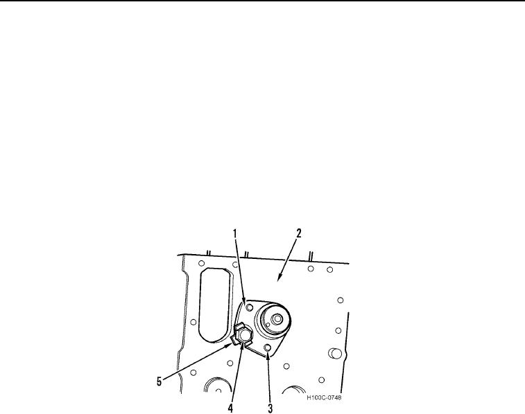
7. Install fan drive idler gear shaft (Figure 13, Item 1) on crankcase (Figure 13, Item 2), aligning marks made on
dowel (Figure 13, Item 3) and casting before removal. Install a lock (Figure 13, Item 5) and bolt (Figure 13,
Item 4). Torque bolt to 150 lb-ft (203 Nm). Bend two lock tabs in to capture hex head.
Figure 13. Fan Idler Gear Shaft in Correct Position.
0097
0097-13

