
TM 5-3805-255-14
0097
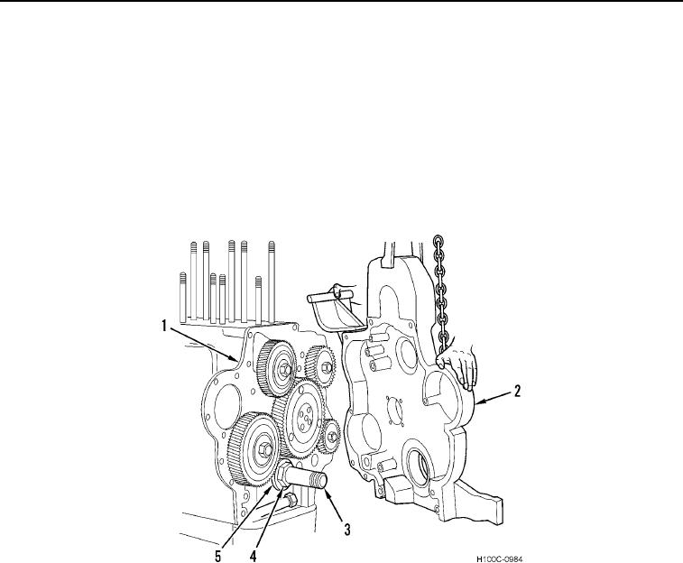
INSTALLATION CONTINUED
15. Install oil slinger (Figure 18, Item 5) and crankshaft gear nut (Figure 18, Item 4) on crankshaft (Figure 18, Item
3). Use wrench adapter and torque crankshaft gear nut to 525 lb-ft (712 Nm). When using wrench adapter,
reading on torque wrench should be 438 lb-ft (594 Nm).
NOTE
Gasket between suction pipe and front cover must be installed with color-coded side of
gasket against front cover, which is UP side.
16. Apply sealer to gasket surface of front cover (Figure 18, Item 2) and crankcase front plate (Figure 18, Item 1)
and install a new front cover gasket.
Figure 18. Gear Train Front Cover Installation.
0097
0097-17