TM 5-3805-255-14
0097
INSTALLATION CONTINUED
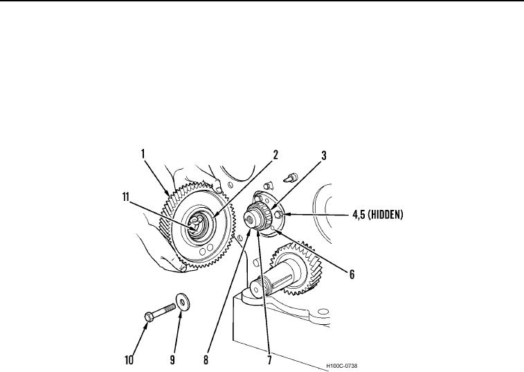
8. Install hydraulic pump idler gear shaft (Figure 14, Item 8), three bolts (Figure 14, Item 4), and locks (Figure 14,
Item 5). Torque bolts to 225 lb-ft (305 Nm). Bend two lock tabs in to capture each hex head.
9. Slide fan drive idler gear bearing cone (Figure 14, Item 3) and spacer (Figure 14, Item 7) onto shaft (Figure 14,
Item 8).
10. Install fan drive idler gear (Figure 14, Item 1), bearing outer cone (Figure 14, Item 11), and bearing race (Figure
14, Item 2) on shaft (Figure 14, Item 8). Install bearing retainer (Figure 14, Item 9) and idler shaft bolt (Figure
14, Item 10) on idler gear shaft. Rotate gear to seat bearing and torque bolt to 150 lb-ft (203 Nm).
Figure 14. Hydraulic Pump Idler Gear Installation.
0097
0097-14

