
TM 5-3805-255-14
0097
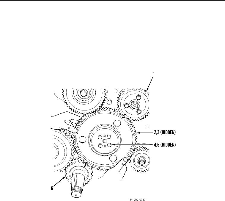
INSTALLATION CONTINUED
NOTE
One of the camshaft locating dowel pins is off-center, preventing gear from being installed
out-of-time.
11. Install camshaft gear (Figure 15, Item 2) so that timing marks stamped on crankshaft gear (Figure 15, Item 6),
injection pump drive gear (Figure 15, Item 1), and camshaft gear are aligned.
12. Install four new camshaft gear lockwashers (Figure 15, Item 5) and bolts (Figure 15, Item 4). Torque bolts to
90 lb-ft (122 Nm).
Figure 15. Camshaft Gear Installation.
0097
0097-15