
TM 5-3805-255-14
0097
INSTALLATION CONTINUED
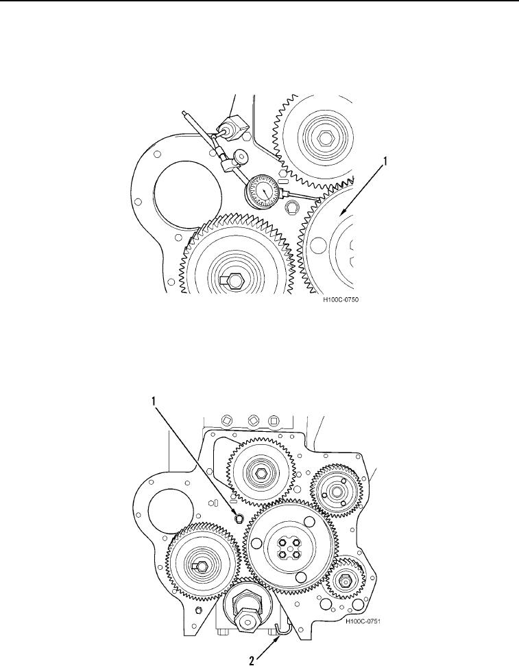
13. Measure backlash between every set of gears with a dial indicator and magnetic base as shown in Figure 16.
Specified backlash between any pair of gears is 0.003 to 0.007 in. (0.08 to 0.18 mm). Maximum permissible
backlash between any pair of gears before service is necessary is 0.011 in. (0.28 mm).
Figure 16. Backlash Measurement.
0097
14. Check to be sure that gear train upper oil spray jet (Figure 17, Item 1) and lower lubricating oil spray jet (Figure
17, Item 2) are set at correct angle as shown in Figure 17. These spray angles are the most effective way to
lubricate all gears in gear train.
Figure 17. Gear Train Lubricating Oil Spray Jets.
0097
0097-16