TM 5-3805-255-14
0100
INSTALLATION
000100
1. Crank engine until TC mark on vibration damper is in line with timing pointer on crankcase front cover. Make
sure No. 1 piston is on TDC of compression stroke.
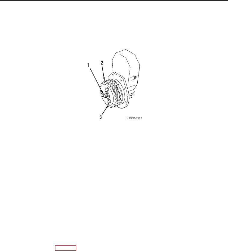
2. Rotate pinion shaft (Figure 13, Item 1) until mark (Figure 13, Item 3) on drive gear (Figure 13, Item 2) is at six
o'clock position.
Figure 13. Drive Gear Phasing.
0100
3. Install assembled adapter housing on crankcase front cover, aligning mark on camshaft gear with mark on
drive gear. Secure adapter housing to crankcase front cover.
4. Install and secure front three capscrews in push rod chamber cover.
5. Connect tube (Figure 14, Item 1) to tee (Figure 14, Item 5). Secure two clips (Figure 14, Item 2) to crankcase
with two capscrews (Figure 14, Item 3). Tighten capscrews securely.
6. Connect tube (Figure 14, Item 4) to tee (Figure 14, Item 5).
7. Install a new gasket onto pump mounting flange of adapter housing.
8. Rotate engine crankshaft clockwise (as viewed from fan drive end) to 38 degrees with No. 1 cylinder on
compression stroke.
9. Loosen three bolts on drive gear and rotate pinion shaft so bolts are approximately halfway between center of
elongated holes and clockwise end of drive gear.
NOTE
Pump shaft will not stay in location but will rotate counterclockwise (as viewed from drive
end of pump) approximately 12 degrees to stable stationary position. Allow pump shaft to
remain in this position.
10. Position injection pump camshaft so that pointer aligns with timing mark on gear.
11. Install pump on engine (WP 0028).
0100-10

