
TM 5-3805-255-14
0100
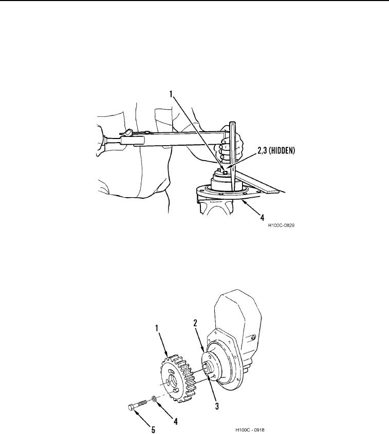
ASSEMBLY CONTINUED
6. Install injection pump hub holding tool on hub (Figure 11, Item 2) and two bolts (Figure 11, Item 1).
7. Install a suitable drift into hole in adapter housing (Figure 11, Item 4).
8. Install pinion nut (Figure 11, Item 3) on end of pinion shaft. Torque pinion nut to 160 lb-ft (217 Nm).
9. Remove drift, two 3/8 NF x 1 1/8 in. bolts (Figure 11, Item 1), and holding tool from housing (Figure 11, Item 4).
Figure 11. Torquing Pinion Shaft Nut.
0100
10. Install drive gear (Figure 12, Item 1) on pinion shaft (Figure 12, Item 3). Install three washers (Figure 12,
Item 4) and bolts (Figure 12, Item 5) into hub (Figure 12, Item 2) finger-tight only.
Figure 12. Drive Gear Installation.
0100
END OF TASK
0100-9