
TM 5-3805-255-14
0102
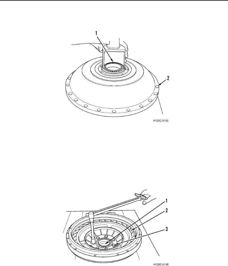
ASSEMBLY CONTINUED
29. Install bearing (Figure 40, Item 1) on impeller (Figure 40, Item 2).
Figure 40. Impeller Bearing Installation.
0102
NOTE
Units may be equipped with either 5/16 or 7/16 in. capscrews. Identify size prior to
installation.
30. Install accessory drive gear (Figure 41, Item 1) in impeller (Figure 41, Item 2).
31. Install seven retaining capscrews (Figure 41, Item 3) and torque 5/16 in. capscrews to 36 to 43 lb-ft (49 to
57 Nm). Tighten 7/16 in. capscrews to 50 to 60 lb-ft (68 to 81 Nm).
Figure 41. Impeller Installation.
0102
0102-25