
TM 5-3805-255-14
0102
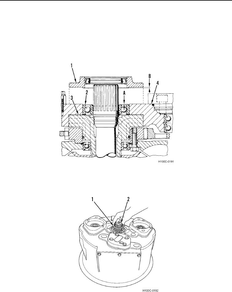
ASSEMBLY CONTINUED
19. Be sure output shaft bearing (Figure 34, Item 2) is flush against ground sleeve hub (Figure 34, Item 3). Using a
depth micrometer, measure distance between machined surface of housing (Figure 34, Item 4) and top of
bearing race (Dimension A).
20. Measure height of lip on bearing retainer (Figure 34, Item 1) (Dimension B).
21. Subtract height of lip from depth of bearing (Dimension A minus Dimension B). The remainder, plus measured
thickness of retainer-to-housing gasket, equals thickness of shim pack to be used in step 23.
Figure 34. Shim Pack Thickness Determination.
0102
22. Install yoke spacer (Figure 35, Item 1) on output shaft (Figure 35, Item 2).
Figure 35. Yoke Spacer Installation.
0102
0102-22