
TM 5-3805-255-14
0102
ASSEMBLY CONTINUED
NOTE
Press on bearing outer race only.
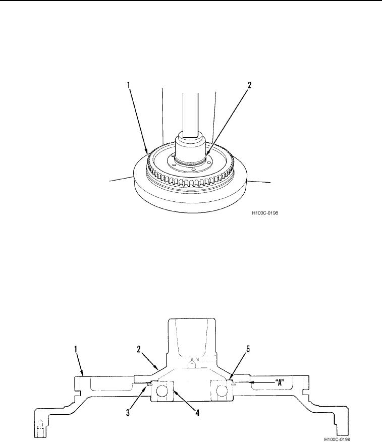
32. Install bearing (Figure 42, Item 2) into drive housing (Figure 42, Item 1).
Figure 42. Turbine Hub Bearing Installation.
0102
33. Install snap ring (Figure 43, Item 3) on bearing (Figure 43, Item 4).
34. Install original shim pack in position (Figure 43, Item 5) on outer race of bearing (Figure 43, Item 4).
35. Place input hub (Figure 43, Item 2) in position over shims (Figure 43, Item 5) and bearing (Figure 43, Item 4).
36. Apply pressure to top of hub and check clearance at "A" between hub and drive housing (Figure 43, Item 1)
flange surfaces.
Figure 43. Clearance Determination.
0102
0102-26