
TM 5-3805-255-14
0103
ASSEMBLY CONTINUED
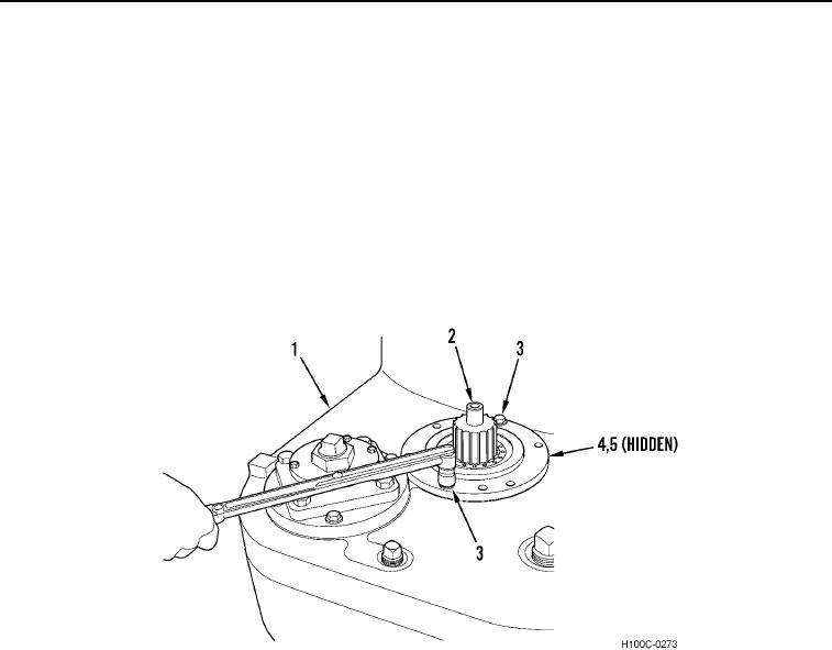
45. Secure transmission housing (Figure 63, Item 1) in vertical position. Grasp end of output shaft (Figure 63,
Item 2) where it protrudes from loose retainer (Figure 63, Item 4), "roll" shaft into opposite (tightened) retainer.
Exert a heavy pressure (thrust) in this direction. This "rolling in" procedure is designed to seat bearing (Figure
63, Item 5) squarely and firmly in its retainer.
46. Loosen two bolts (Figure 63, Item 3) installed previously in output shaft retainer (Figure 63, Item 4). Torque
bolts to preliminary torque of 25 to 30 lb-in. (0.18 to 0.21 Nm).
NOTE
Continue to "roll" output shaft while torquing bolts.
47. Rotate output shaft (Figure 63, Item 2) several times. Torque two bolts (Figure 63, Item 3) to secondary torque
of 50 lb-in. (0.35 Nm).
Figure 63. Output Shaft Bearing Seat Procedure.
0103
0103-41