
TM 5-3805-255-14
0103
ASSEMBLY CONTINUED
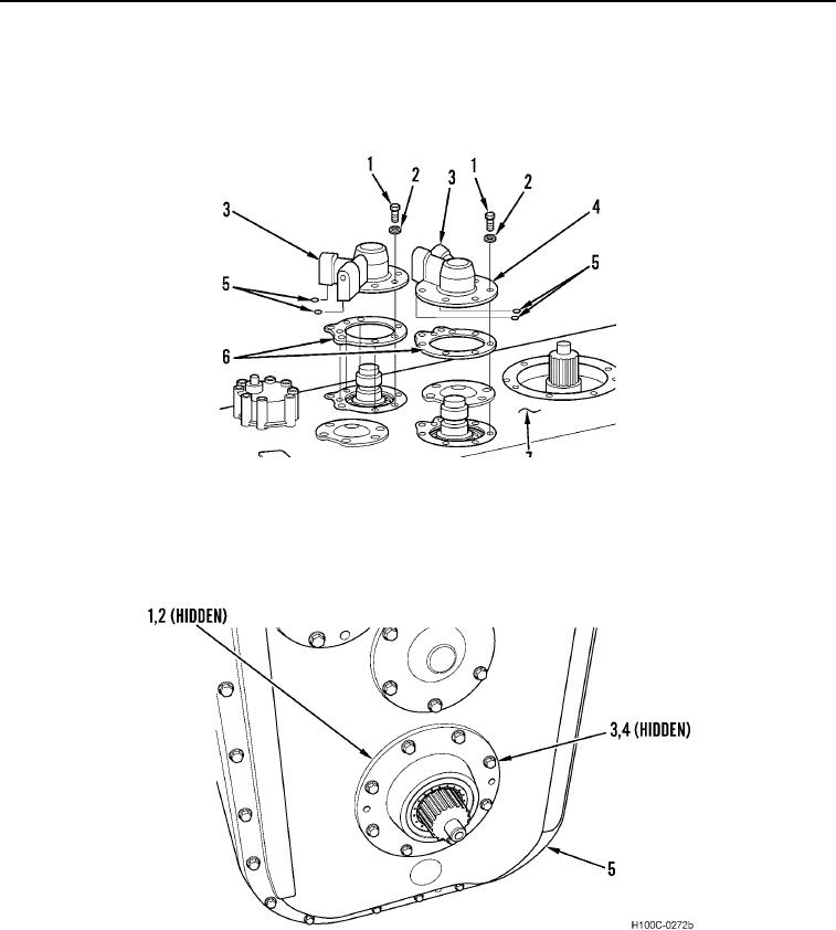
41. Install four new O-rings (Figure 61, Item 5) on two range clutch oil supply covers (Figure 61, Items 3 and 4).
42. Install oil supply covers (Figure 61, Items 3 and 4), 12 new lockwashers (Figure 61, Item 2), and 12 bolts
(Figure 61, Item 1) on transmission housing (Figure 61, Item 7). Torque bolts to 33 to 37 lb-ft (45 to 50 Nm).
Figure 61. Oil Supply Covers Installation.
0103
43. Install new O-ring (Figure 62, Item 2) on output shaft front retainer (Figure 62, Item 1).
44. Install output shaft front retainer (Figure 62, Item 1), eight new lockwashers (Figure 62, Item 4), and bolts
(Figure 62, Item 3) on transmission cover (Figure 62, Item 5). Torque bolts to 33 to 37 lb-ft (40 to 50 Nm).
Figure 62. Output Shaft Front Retainer Installation.
0103
0103-40