TM 5-3805-255-14
0104
ASSEMBLY CONTINUED
NOTE
Steps 18 through 22 apply to both sides of clutch pack
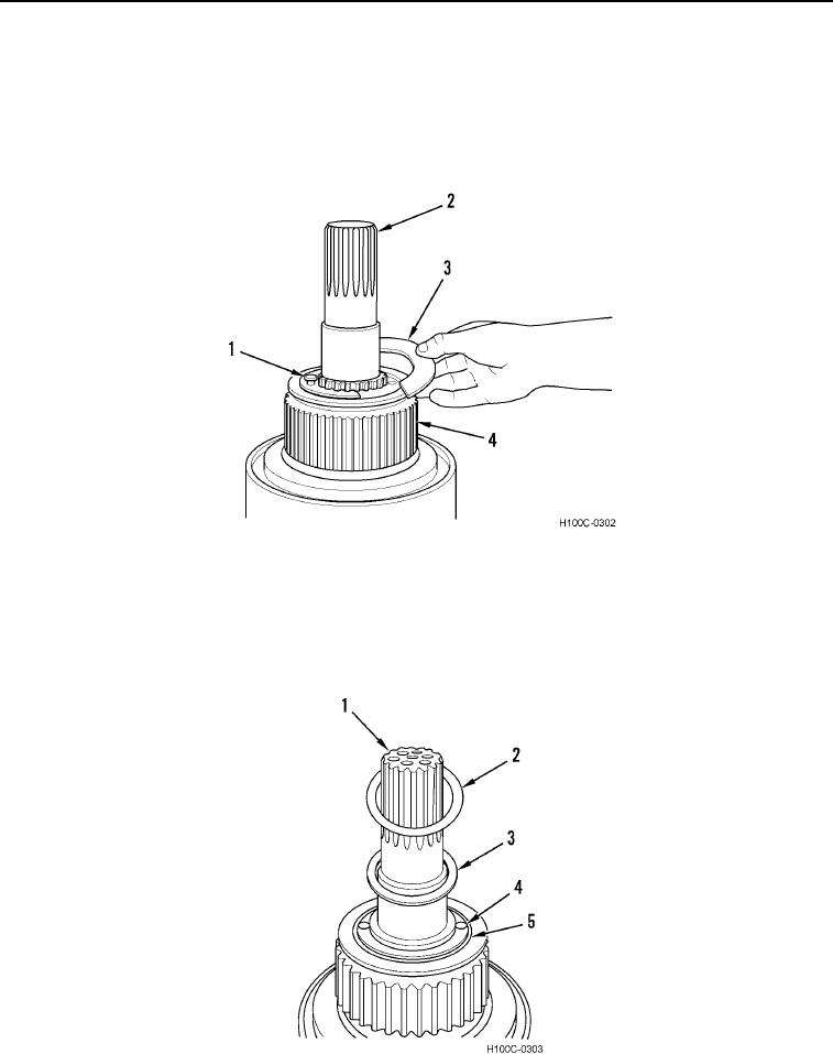
18. Install hub assembly (Figure 29, Item 4), two hub retainers (Figure 29, Item 3), and capscrews (Figure 29,
Item 1) on clutch shaft (Figure 29, Item 2). Torque capscrews to 33 to 37 lb-ft (40 to 50 Nm).
Figure 29. Hub and Hub Retainer Installation.
0104
19. Install spacer (Figure 30, Item 5) and two locking retainer bolts (Figure 30, Item 4) on clutch shaft (Figure 30,
Item 1).
20. Coat bronze thrust washer (Figure 30, Item 3) with grease and install bronze thrust washer and thin spacer
washer (Figure 30, Item 2) on shaft (Figure 30, Item 1).
Figure 30. Shaft Assembly.
0104
0104-16

