
TM 5-3805-255-14
0104
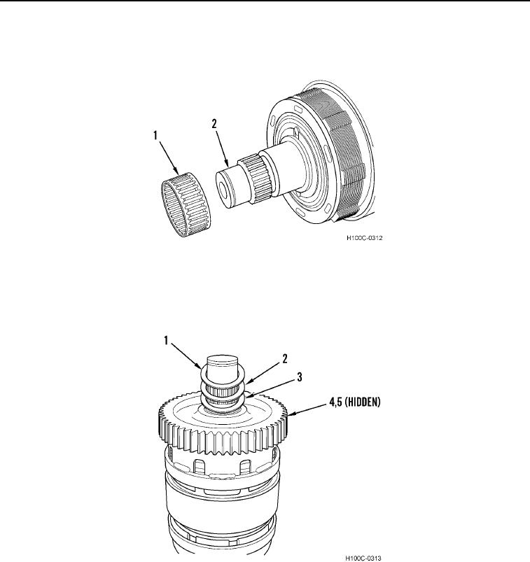
ASSEMBLY CONTINUED
4. Install roller bearing (Figure 39, Item 1) on splined end of clutch shaft (Figure 39, Item 2). Cover rollers with a
coat of grease.
Figure 39. Roller Bearing Installation.
0104
5. Install drive gear and cup assembly (Figure 40, Item 4) (large diameter, narrow gear), spacer washer
(Figure 40, Item 3), bronze thrust washer (Figure 40, Item 2), and spacer washer (Figure 40, Item 1) on clutch
shaft (Figure 40, Item 5).
Figure 40. Drive Gear Installation.
0104
0104-22