TM 5-3805-255-14
0104
ASSEMBLY CONTINUED
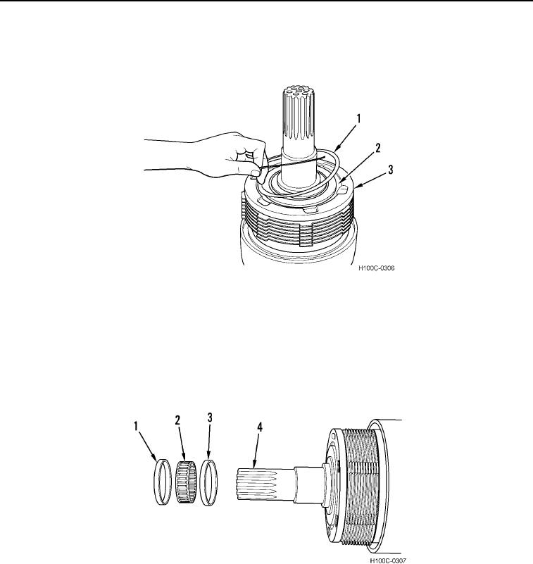
24. Install new retaining ring (Figure 33, Item 1) in backing plate (Figure 33, Item 3). This locks in external snap
ring (Figure 33, Item 2).
Figure 33. Retaining Ring Installation.
0104
NOTE
Heat bearing inner race to 250F (121C) prior to installation.
Directional Clutch
000104
1. Install spacer (Figure 34, Item 3), roller bearing (Figure 34, Item 2), and spacer (Figure 34, Item 1) on splined
end of clutch shaft (Figure 34, Item 4). Cover rollers with a coat of heavy grease.
Figure 34. Roller Bearing and Spacers Installation.
0104
0104-18

