
TM 5-3805-255-14
0104
ASSEMBLY CONTINUED
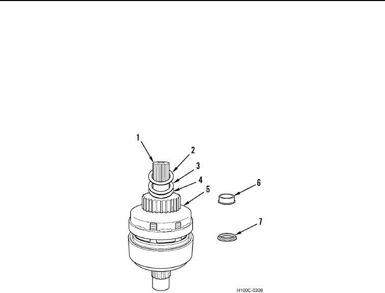
2. Install drive gear and cup assembly (Figure 35, Item 5) (small diameter, wide gear) on clutch shaft (Figure 35,
Item 1).
3. Install spacer washer (Figure 35, Item 4), bronze thrust washer (Figure 35, Item 3), and spacer washer
(Figure 35, Item 2) on clutch shaft (Figure 35, Item 1).
NOTE
Heat bearing inner race to 250F (121C) prior to installation.
4. Install wide spacer (Figure 35, Item 7), with large diameter shoulder toward spacer washer (Figure 35, Item 2),
and heated bearing inner race (Figure 35, Item 6) on clutch shaft (Figure 35, Item 1).
Figure 35. Bearing Race Installation.
0104
0104-19