rpm as would be noticed when shifting lever into
5. Reinstall ball joint assembly in lever arm and
REVERSE position. A steady rpm will give a more
s e c u r e with locknut, then tighten jam nut on
p r o n o u n c e d indication. However, if forward
shift rod.
movement of the machine does occur, this is an
6. Check that levers will shift into all detent posi-
indication that the de-clutch valve is not func-
t i o n s without interference from the steering
tioning properly and must be replaced.
column, bell cranks, bell crank mounting sup-
3. Shut down engine and remove and replace de-
p o r t or transmission control cover and valve
clutch valve.
housing.
4 . Recheck valve operation as described in Steps
C h e c k Transmission De-Clutch Valve: The
1 and 2.
t r a n s m i s s i o n de-clutch valve is an air operated
valve consisting of a piston, piston stop plug, and
Check Converter Internal Pressure: The tor-
the necessary o-rings to provide an air tight body.
q u e converter internal pressure must be main-
This valve is installed in a housing bore containing
tained within the specified limits listed below to
a shut-off valve spool located in the transmission
i n s u r e proper operation of the torque converter
control cover and connected to the brake valve by
and converter regulator valve assembly.
a hose line.
Periodically check the converter internal pres-
The function of the de-clutch valve is to auto-
sure when fluid is at operating temperature
m a t i c a l l y establish a transmission neutral using
(180F. to 200F.) and engine operating at maxi-
air pressure from the brake system when the left
mum rpm.
brake pedal is applied.
1. Shut down engine and remove pipe plug from
When the left brake pedal is applied, the brake
converter regulator valve assembly.
valve releases air pressure from the brake system
2. Install an accurate gauge (0 to 100 psi capacity)
into the de-clutch valve forcing the de-clutch valve
i n regulator valve pressure port as shown in
piston to contact the shut-off valve spool inside the
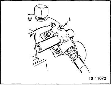
Figure 26, Item 1.
transmission control cover. This forces the shut-off
valve spool to shift into a position that prevents
3. Place directional lever in NEUTRAL and apply
o i l flow to the forward clutch, disengaging the
p a r k i n g brake.
clutch and establishing a transmission neutral. The
4. Start engine and accelerate to maximum rpm.
reverse clutch is not affected.
Gauge reading should be between a maximum
of 60 psi and a minimum of 30 psi.
This arrangement prevents the machine from
c r e e p i n g forward when loading or dumping the
If pressure is not within the specified limits,
bucket; yet permits backing away if operating on
further trouble shooting of the torque converter,
a sloping grade. It also increases the boom and
bucket hydraulic system working power by utiliz-
ing the power contained at the transmission, which
is normally used for engaging the forward clutch
to drive the wheels.
Maintenance consists of periodically checking
t h e de-clutch valve or proper operation as de-
scribed below :
1. Place directional shift lever in NEUTRAL position
and start engine.
2. Accelerate engine to approximately half throt-
tle, lightly apply left brake pedal and shift di-
rectional shift lever to FORWARD position. There
s h o u l d be no clutch engagement (causing the
m a c h i n e to move forward) or drop in engine
Fig.26.
Check Converter Internal Pressure
[45-05-2]

