16. With transmission directional lever in NEU-
TRAL, actuate bucket control lever to the full
D U M P position, maintaining low idle rpm.
Gauge should read 1750 to 2200 psi. If reading
is not as specified, replace bucket dump relief
v a l v e cartridge (Item 4 Figure 31).
IMPORTANT: OVERLOAD RELIEF VALVES ARE PRE-
SET AND SEALED AT THE FACTORY. DO NOT BREAK THE
SEAL. IF THE SEAL IS BROKEN, REPLACE RELIEF VALVE
CARTRIDGE IMMEDIATELY. ADJUSTMENTS ARE TO BE
MADE ONLY AT THE MAIN RELIEF.
Check and Ad just Main Hydraulic Pump : The
main hydraulic pump is a double pump, consisting
of a primary section and a secondary section. At
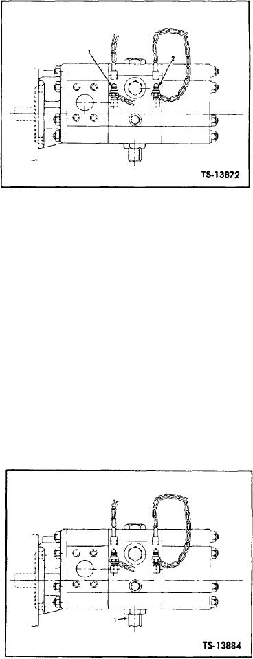
2. Secondary Port
1. Primary Port
l o w e r pressures, up to by-pass pressure setting,
Fig. 34. Main Hydraulic Pump Pressure Ports
b o t h sections supply the main hydraulic system.
From by-pass pressure setting up to system relief,
at specified pressure, it will be necessary to adjust
the pressure sensitive valve attached to the pump
the pressure sensing valve on the main pump. Pro-
causes the secondary section to unload by-passing
ceed with valve adjustment as follows :
back to the suction side, leaving the primary sec-
1. Remove acorn nut and o-ring covering adjust-
tion to supply the system.
i n g screw on pressure sensing valve. See Fig-
ure 35.
Maintenance consists of periodically checking,
and adjusting if necessary, the pressure at which
2. Actuate boom control lever to the raise position
t h e secondary section of the pump unloads and
maintaining low idle rpm. Feather the lever as
by-passes.
b o o m approaches stop, observing the pressure
a t which the secondary section unloads, then
1. Attach safety links and apply parking brake.
return lever to the neutral position.
2. Install two 3000 psi
capacity gauges, one at the
3. Turn pressure adjusting screw in increments of
pressure port on the
primary section and one at
1/4 turn, clockwise to increase or counter-clock-
the pressure port on
the secondary section of the
wise to decrease unloading pressure. Recheck
main pump as shown
in Figure 34, Item 1 & 2.
unloading pressure as described in Step 2. Re-
peat this procedure until secondary section of
3. With transmission directional shift lever in neu-
main pump unloads at specified pressure.
tral, start engine and follow normal warm up
procedure.
4. Actuate boom control lever to the lift position,
maintaining low idle rpm. Raise boom to stop,
f e a t h e r i n g lever as boom approaches stop. Ob-
s e r v e both gauges. As pressure increases, the
gauge attached to the secondary section of the
pump will indicate a sudden drop-off in pres-
s u r e . The highest pressure indicated is the un-
l o a d i n g pressure.
5 . Observe the indicated pressure on the gauge
a t t a c h e d to the main hydraulic pressure port.
W h e n the unloading pressure is reached, this
gauge should read as specified in Specifications
and Service Data section at rear of manual.
1. Acorn Nut
If the secondary pump section does not unload
Fig. 35.
Main Hydraulic Pump Adjustment
[45-05-6]

