8. If bucket ROLLBACK and boom RAISE are not the
same within 50 psi, the circuit with the lower
r e a d i n g must have the relief valve cartridge
on the pilot valve changed. Figure 31 Item 1 is
bucket rollback cartridge Item 2 is boom raise
cartridge.
9. After either relief cartridge is changed, repeat
Steps 6,7,8 and 9 until recorded pressure read-
ings for bucket ROLLBACK and boom RAISE are
the same within 50 psi.
10. If gauge pressure readings or bucket ROLLBACK
and boom RAISE are the same within 50 psi, but
not to specification of 2200 50 psi, the main
relief valve, (located in the main control valve
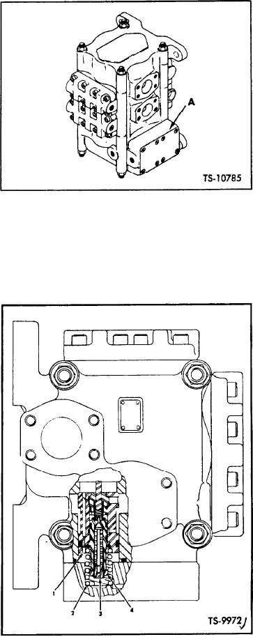
Remove Cover - Main Relief
Fig. 32.
assembly) must be adjusted. See Steps 11 thru
13 for procedure.
15. With transmission directional lever in NEU-
TRAL, feather boom control lever to the DOWN
11. Remove eight bolts retaining cover (Figure 32,
PRESSURE position, maintaining low idle rpm.
Item A) and remove cover. Refer to Figure 33
Gauge should read 1750 to 2200 psi. If reading
a n d remove spring (Item 2) and main relief
is not as specified, replace down pressure relief
valve assembly (Item 1), which protrude from
v a l v e cartridge (Item 3 Figure 31).
face of main control valve after cover is re-
moved. Refer to Figure 33 and loosen hex lock-
nut portion (Item 4) of relief valve and turn
adjusting screw (Item 3) clockwise to increase
pressure or counter-clockwise to decrease pres-
s u r e . Each complete turn of adjusting screw
changes setting approximately 1600 psi. Exam-
ple : If pressure reading recorded in Step 9 was
1 4 0 0 psi, 1/2 turn (clockwise) of adjusting
screw would raise relief valve pressure to 2200
psi. After adjusting, tighten locknut.
12. Reinstall relief valve assembly and spring in
position in main valve assembly.
IMPORTANT: Adjusting screw and locknut
portion of relief valve must be toward outside
of valve.
13. Reinstall cover using two bolts in diagonally
o p p o s i t e holes in cover. Springs under cover
m u s t be compressed to start bolts into hole
t h r e a d s . Turn bolts finger tight. Install re-
maining bolts finger tight. Using a torque
wrench with adapter for 3/8 inch Allen wrench,
torque all bolts to 60-75 ft. lbs.
14. Place transmission directional and speed range
levers in FORWARD, HI, actuate bucket control
3. Adjusting Screw
Relief Valve Assy.
lever to full ROLLBACK position and accelerate
2. Spring
4. Locknut
to maximum rpm. Gauge should read 2200
5 0 psi..
Main Relief Valve
Fig. 33.
[45-05-5]

