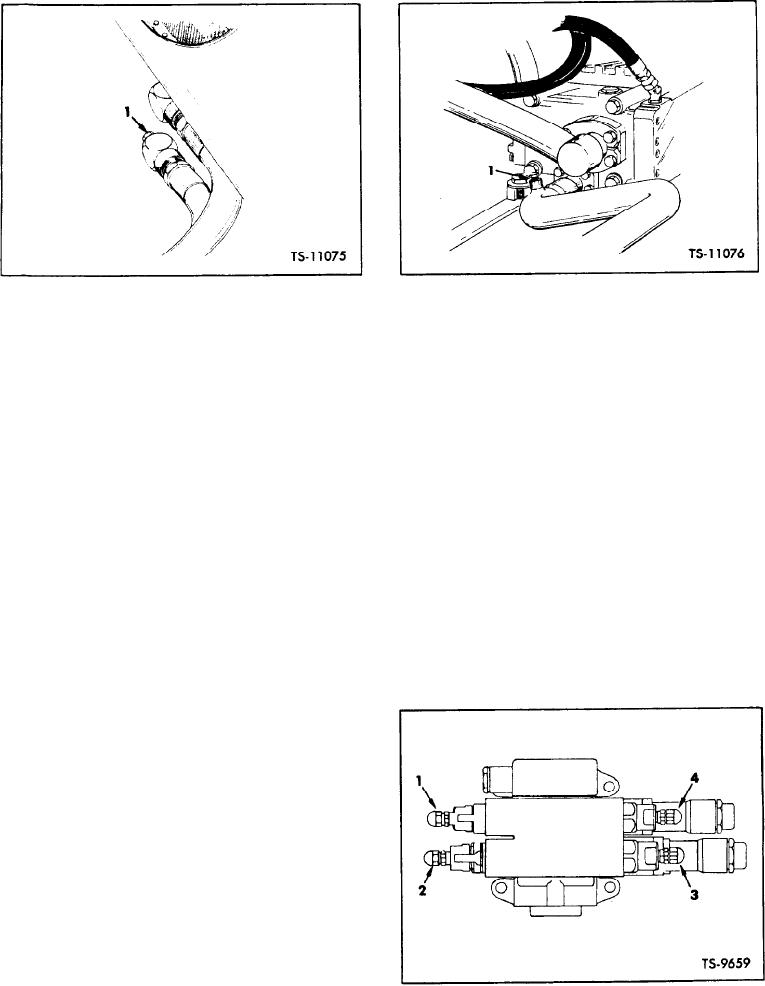
1. Pipe Plug
1. Pressure Port
Main Hydraulic Pressure Gauge Port
Fig. 30.
Check Pressure - Oil Cooler OUT
Fig. 29.
ure 30 for typical gauge installation.
3. With the aid of a helper, read gauges at steady
2000 rpm, and subtract oil cooler OUT Pressure
4 . Place transmission directional shift lever in
from oil cooler IN pressure to get pressure drop.
N E U T R A L , start engine and apply parking
Pressure drop should be between 10 psi and 30
brake.
psi.
5. If it is necessary during any of the following
steps to replace any of the relief valve cart-
If pressure difference equals or exceeds 30 psi
ridges on the pilot valve, remove seat and seat
it will be necessary to thoroughly clean or replace
support plate to gain access to pilot valve.
the oil cooler and/or the radiator assembly.
6. With transmission directional and speed range
levers in FORWARD, and HI, actuate bucket con-
Check Boom and Bucket Pressure: The boom
trol lever to ull ROLLBACK position and acceler-
and bucket hydraulic pump is coupled to the drive
a t e engine to maximum rpm. Record gauge
line and operates as soon as the engine starts. The
reading and proceed to Step 7.
pump draws fluid from the reservoir and forces it
under pressure into the main hydraulic valve, from
7. With transmission directional and speed range
which a small supply of fluid is directed to the pilot
levers in FORWARD, and HI, actuate boom con-
valve, routing the fluid back to the main valve, op-
trol lever to the full RAISE position and acceler-
erating the desired circuit in the main valve, sup-
a t e engine to maximum rpm. Record gauge
p l y i n g the flow of fluid to the cylinders. Preset
reading and proceed to Step 8.
overload relief cartridges on the pilot valve protect
the system and components.
Maintenance consists of periodically checking
the pressure in the system. All pressure checks are
to be made with fluids at operating temperature.
( 1 5 0 F . minimum),
1. Attach safety links and block wheels.
2. Use a hydraulic test gauge of at least 3000 psi
capacity. With engine shut down, loosen cap
o n hydraulic reservoir until pressure escapes,
t o minimize oil loss while attaching gauge,
then retighten cap.
3. Remove pipe plug from pressure port on main
pressure tube, and attach gauge. Refer to Fig-
Pressure Relief Cartridges - Pilot Valve
Fig. 31.
[45-05-4]

