
Engine Systems
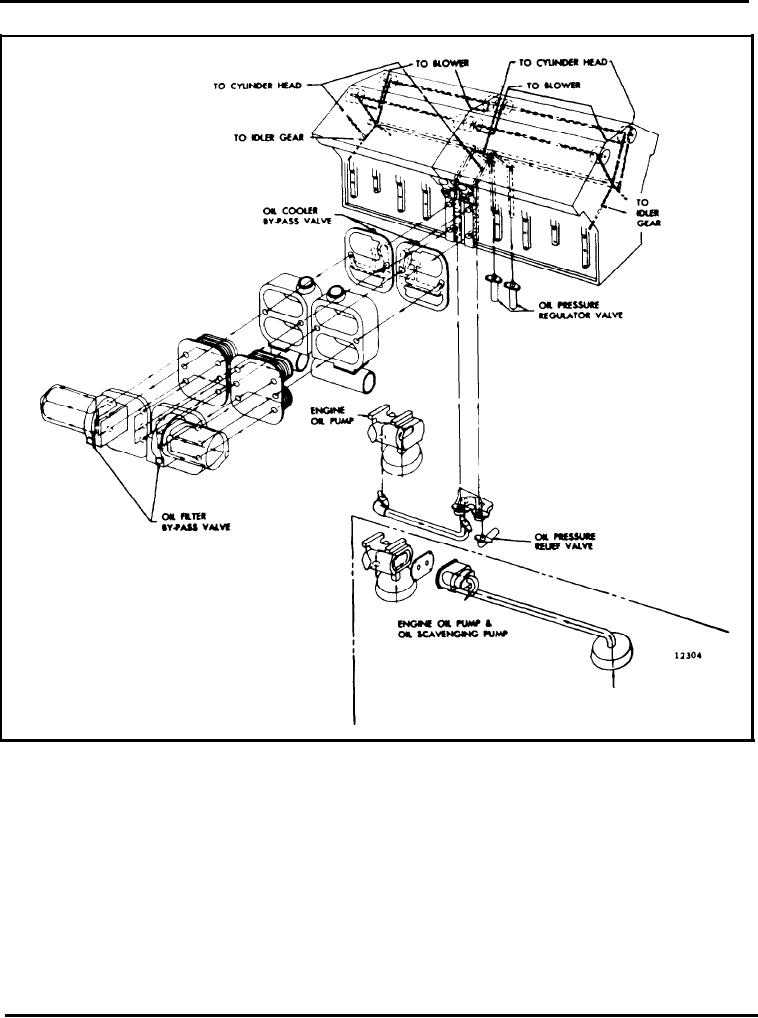
Fig. 17 - Schematic Diagram of Typical 16V Lubrication System
filters a portion of the lubricating oil that is being bled
type oil filter may also be installed. The full-flow filter
assembly can be remotely mounted or mounted on the
off the oil gallery when the engine is running.
engine as shown in Fig. 18. A by-pass valve, which
Eventually all of the oil passes through the filter,
opens at 15 psi (103 kPa), is located in the filter base
filtering out minute foreign particles that may be
to ensure engine lubrication in the event the filter
present.
should become plugged.
Some engines may be equipped with a by-pass filter
All of the oil supplied to the engine passes through the
assembly consisting of two filter elements, each
full-flow filter that removes the larger foreign particles
enclosed in a shell which is mounted on a single base.
without restricting the normal flow of oil.
An oil passage in the filter base connects the two
annular spaces surrounding both filter elements.
The by-pass filter assembly, when used, continually
Page 24