Engine Systems
LUBRICATING SYSTEM
bearings. The blower drive gear is lubricated from the
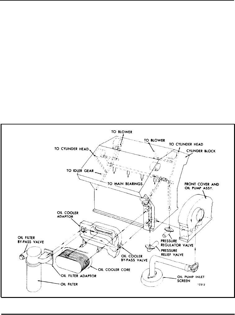
The lubricating oil systems schematically illustrated in
rear of the blower.
Figs. 15, 16 and 17 consist of an oil pump, oil cooler,
a full-flow oil filter, by-pass valves at the oil cooler
The oil pump on the 6 and 8V engines is driven by a
and filter and pressure regulator valves at the pump
pump drive hub on the front end of the crankshaft
and in the cylinder block main oil gallery. Positive
and consists of a large and small spur gear meshing in
lubrication is ensured at all times by this system. A
a cavity inside the crankshaft cover.
by-pass oil filter may also be incorporated into the
lubricating system at the owner's option.
The gear-type oil pump used on the 12 and 16V
engines is mounted on the main bearing caps. The
pump on the 12V engine is driven from the front end
Oil for lubricating the connecting rod bearings and
of the crankshaft and on the 16V engine the pump,
piston pins and for cooling the piston head is provided
which is mounted on the No. 9 and 10 main bearing
through the drilled hole in the crankshaft from the
caps, is driven from the rear end of the crankshaft.
adjacent forward main bearings. The gear train is
lubricated by the overflow of oil from the camshaft
The pressure regulator valve, located at the end of a
pocket through a connecting passage into the flywheel
vertical oil gallery in the front of the cylinder block,
housing. A certain amount of oil spills into the
maintains a stabilized oil pressure. The l6V engine
flywheel housing from the camshaft and idler gear
has two pressure regulator valves located at the ends of
Fig. 15 - Schematic Diagram of Typical 6V and 8V Lubricating Systems
Page 22

