Engine Tune-Up
injector racks must respond in the same manner on the
ball ends of their respective rack control levers as in
Step 6.
10. Position the remaining injector rack control levers
on the right front cylinder head in the same manner.
When the settings are correct, all of the injector racks
will be snug on the ball end of the control levers when
the injector control tube is in the full-fuel position.
11. Adjust the remaining injector rack control levers
on the right rear, left front, and left rear cylinder
heads in the same manner as in Steps 8, 9 and 10.
12. Reconnect the upper end of the adjustable vertical
link on the differential lever pin and secure it in place
with the washer and clip.
13. To be sure that the governor flyweights will be in
the vertical position throughout the intermediate speed
range (between idle speed and full-load speed), adjust
the vertical link as follows.
a. Loosen and back off the two turnbuckle lock nuts
two or three turns.
b. Secure the speed control lever in the maximum
speed position.
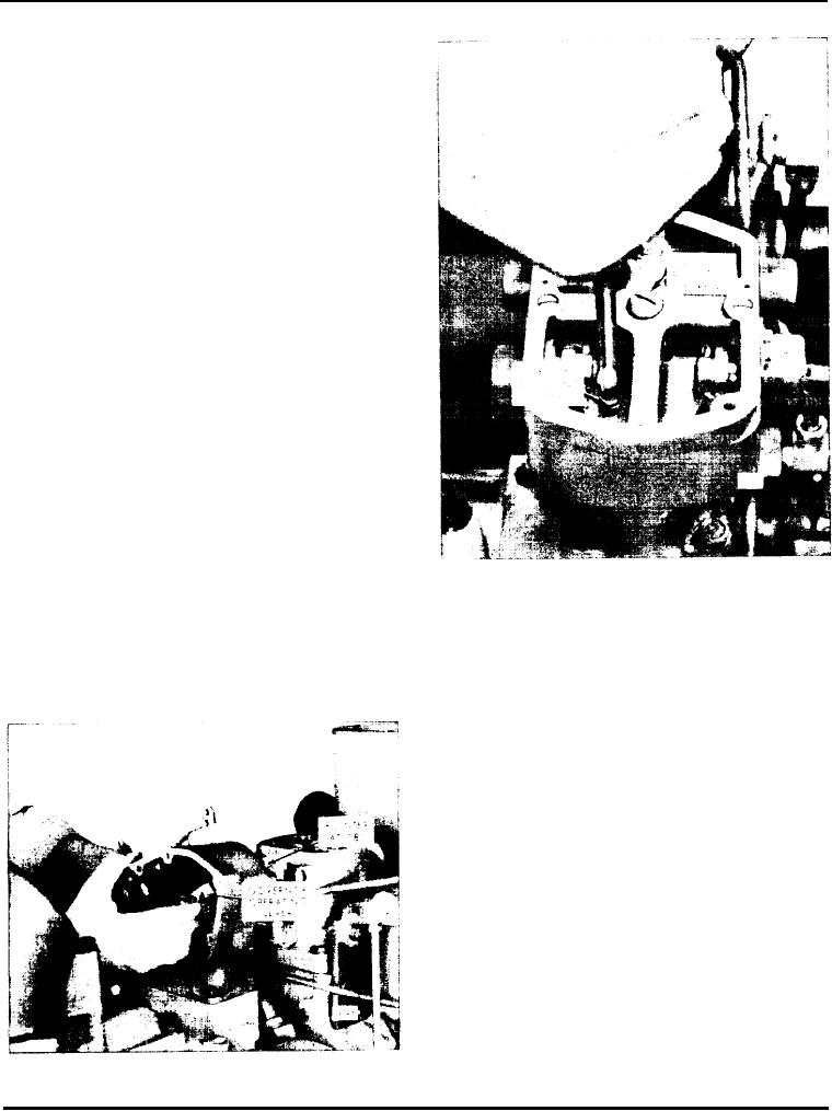
Fig. 7 - Adjusting Speed Droop
c. Reach in behind the differential lever in the
NOTE: It is very important that the force to
governor control housing and force the governor
m o v e the pointer to 18 be applied to the
operating lever upward until the governor pointer
governor operating lever rather than to the
is aligned exactly with the 18 mark (Fig. 6). Hold
differential lever. This is necessary to ensure
the lever in this position.
that the terminal lever pin is tight against the
upper side of the slot in the differential lever
just as it is when the engine is running under
governor control.
d. Adjust the length of the vertical link, by means of
the turnbuckle, so the injector racks are in the
full-fuel position. Then tighten the lock nuts.
e. Recheck to determine if the pointer still points to
exactly 18 when the injector racks are at the full-
f u e l position. Readjust the vertical link, if
necessary.
f. Release the speed control lever. With the lever in
the idle speed position, the pointer should be at
approximately 18.
14. Use a new gasket and install the valve rocker cover
on each cylinder head.
Page 135

