Engine Tune-Up
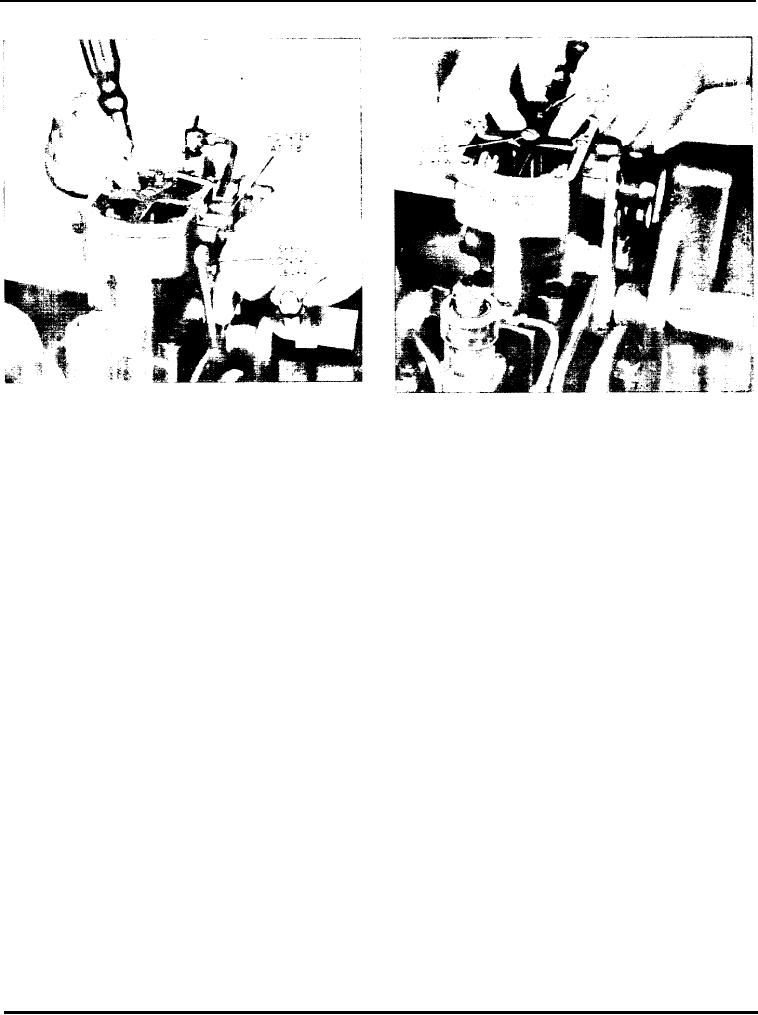
Fig. 9 - Moving Flyweight with Screw Driver
Fig. 10 - Adjusting Band-Level
moving the linkage so the pointer is near the
assembly. Make sure the pin in the speed droop
36 mark.
adjusting bracket enters the slot in the floating lever.
CAUTION: Hold the idle speed spring seat or
6. Reset the band--level adjustment.
spring with your finger, as shown in Fig. 11, to
p r e v e n t it from falling into the governor
7. Reset the idle speed
housing.
8. Check the maximum speed.
2. Loosen the small set screw (on the side opposite the
9. Check the engine speed by suddenly moving the
anti-rotating pin) in the high speed spring cage with a
speed control lever from idle to maximum. If the
5/64" Allen wrench (Figs. 8 and 12).
engine speed does not stabilize after two to four
surges, move the droop bracket outward. Recheck the
idle and maximum speeds.
3. Turn the high speed adjusting nut up to decrease or
down to increase the speed (Fig. 13).
10. Install the governor cover and tighten the screws.
NOTE: A 1/6th turn of the nut changes the
speed 30-40 rpm. Use a 1/4" Allen wrench (the
end of the wrench should be ground flat or
Adjust Buffer Screw
slightly concave).
The purpose of the buffer screw adjustment is to
prevent the injector racks from going all the way to
4. Tighten the small set screw to lock the adjusting nut
the no-fuel position and causing the engine to stall.
in place.
1. With the warm engine at idle, turn the buffer screw
in until it just touches the lower left end of the
5. Check to make sure the idle speed adjusting pin is
differential lever Then, back off three complete turns
in position and place the idle speed spring against the
and tighten the lock nut.
spring seat. Then, holding the spring in place with
your finger (Fig. 11) and holding the linkage so the
2. Install the cover on the governor control housing
pointer is near the 36 marl, install the sub-cap
Page 138

