
Engine Tune-Up
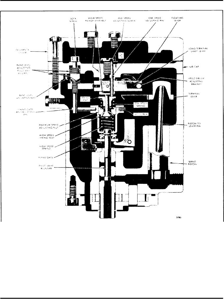
Fig. 8 - Cross-Section of Limiting Speed Hydraulic Governor for 16V Engine
d. Reset the idle speed, if the band-level has been
c. If the pointer indicates less than 18 at approxi-
changed.
mately 300 rpm below the top no-load, speed, the
band-level is too high. The adjusting nut should
be turned counterclockwise, in small increments,
A d j u s t Maximum No-Load Speed
until the pointer indicates exactly 18 at the above
speed. If the band-level is too high, the engine
1. Remove the sub-cap assembly, including the idle
speed may fall several hundred rpm below the top
speed spring. Since the sub-cap is dowelled to the
no-load speed even though the speed control lever
governor housing, removal will be made easier by
is in the maximum speed position.
Page 137