
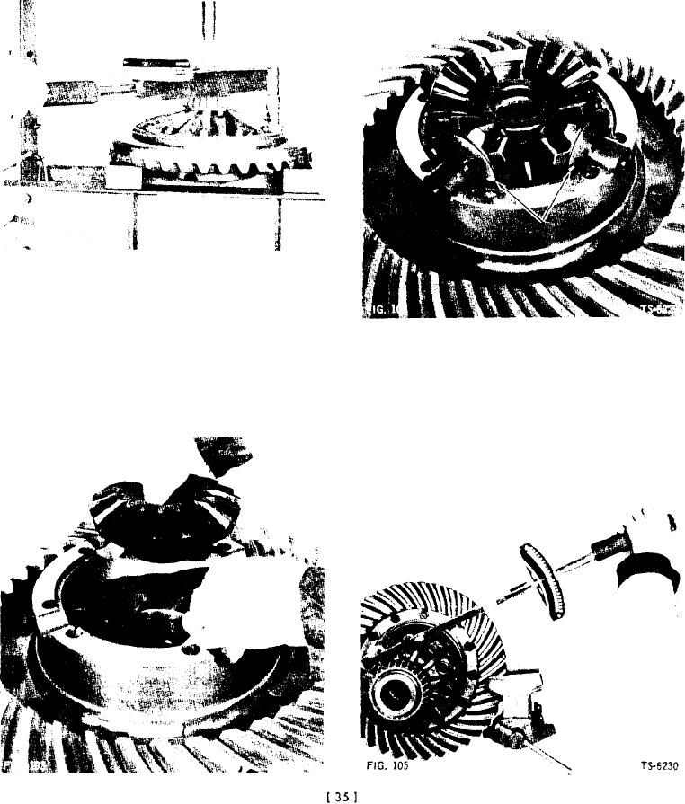
3. Install ring gear. Install bolts so internal diameter of
2. Place pinions and thrust washers on differential spider,
ring gear prevents turning of hex head. Install ring
lubricate, and set in position on installed side gear.
gear bolt nuts and torque to 120 to 135 ft. Ibs. Posi-
NOTE: It is very important that tong on each pinion
tion ring gear and flanged hub in press and apply light
thrust washer engages groove in case halves as shown
press pressure to facilitate torquing nuts (Fig. 102).
by arrows in Fig. 104.
NOTE: Axle Part Nos. 130788, 131507, and 190010
are equipped with No SPlN differentials. Refer to Figs.
107 through 118 for reassembly instructions.
3. Align match-marks and install remaining case half on
Reassembly of Conventional Differential
other case half assembly, making sure of full gear en-
1. Lubricate and install thrust washer and side gear in
gagement (Fig. 105). Install bolts and tighten to speci-
differential case and ring gear assembly (Fig. 103). En-
fied torque.
gage holes in thrust washer on dowels projecting from
NOTE: Some differential cases are held together with
thrust washer bearing surface in differential case.
thru bolts and self-locking nuts instead of bolts in
tapped holes. The bolt heads must extend from the
ring gear side of the case assembly.