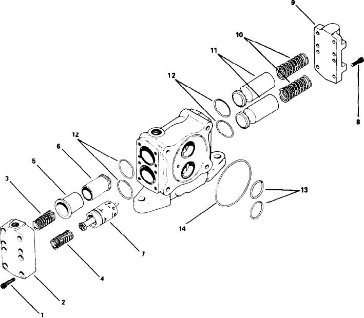
INLET SECTION
Examine all springs for breaks or distortion. In-
spect all poppet seating surfaces for nicks or ex-
cessive wear. All seats must be sharp and free of
nicks. All bores and surfaces of sliding parts must
be free of nicks scores or excessive wear. Insert
the poppets (11) into their respective bore and test
for fit. Poppets should fit snugly, without binding
through a complete revolution. Follow same pro-
cedure to check fit between the sleeve (5) and low
pressure relief valve (6).
DISASSEMBLY
Examine all O-rings and back-up rings for dam-
Note the position of parts during disassembly so
age or deterioration. Replace defective parts.
they can be reassembled in the correct position.
Mark both covers (2 & 9) to insure correct reas-
ASSEMBLY
sembly. Remove the eight socket screws (1) and
inlet cover (2). Remove springs (3 &. 4) and tag for
Coat all parts including housing bores with hy-
p r o p e r reassembly. Remove low pressure relief
d r a u l i c oil. Insert poppets (11) and springs (10)
valve sleeve (5) with subassembly (6) and main
i n t o their respective bores. POPPETS MUST BE
relief valve subassembly (7).
INSTALLED IN CORRECT POSITION.
R e m o v e the eight socket screws (8), poppet
Place O-rings (12, 13, &. 14) into their corre-
c o v e r (9) springs (10) and poppets (11). Remove
sponding grooves. A light coating of grease will
all external O-rings (12, 13, & 14) from inlet housing.
hold them in place. Attach blank cover (9) with
socket screws (8) and hand tighten.
INSPECTION
Mate low pressure relief (6) with sleeve (5). In-
C l e a n all parts, i n c l u d i n g subassemblies, in
sert this subassembly along with relief valve (7)
solvent and dry with compressed air. Inspect the
and spring (3 & 4) into their respective bore. Attach
hole and ball poppet of low pressure subassembly
inlet cover (2) with socket screws (1) and tighten
(6) for foreign particles, clean with compressed air.
to 60 ft. lb. (8,3 kg. mtrs.).
[ 29 ]

