
PILOT VALVE PLUNGER SECTION
DISASSEMBLY
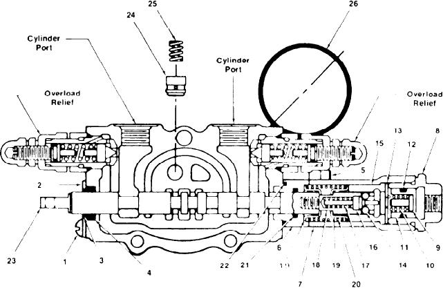
Remove two socket screws (5) securing spacer (6)
and plunger cap (7). Slide the plunger as a com-
With the exception of the valve plunger and
plete assembly from the section housing. With a
plunger housing, all parts are considered field ser-
firm grip on the plunger cap (7) unscrew pilot
viceable. Should either plunger or housing be de-
plugs (8) and remove pin (9), spring (10), pistons
fective, it is recommended to replace the complete
(11), O-ring (12) and spacer (13). Place tang end
plunger section. If any emergency situation neces-
of plunger (23) in a vise. To prevent losing the de-
sitates field repair of the plunger or section hous-
tent balls (14) wrap a cloth around the plunger cap
ing, refer to the emergency repair instructions.
(7) and with a swift jerk remove the plunger cap
(7). Remove detent sleeve (15), balls (14), cam (16)
The internal parts of the boom and bucket plung-
and spring (17). Insert a rod through the cross hole
er sections are similar therefore this disassembly
in the detent pin (18) and unscrew it from the plung-
procedure pertains to both. Begin disassembly by
er. Slight pressure should be exerted against the
removing the cylinder port relief valve from plung-
detent pin (18) as it disengages and spring tension
er sections. Proceed to service the section by re-
is released. Remove spring seats (19) plunger
moving machine screws (1), seal plate (2), wiper
spring (20), cap spacer (6) and two O-rings (21 &
(3) and O-ring (4) from the tang end of plunger.
22) from the cap spacer.
[34]