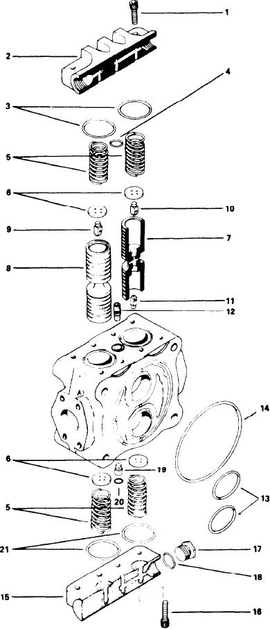
DISASSEMBLY
BOOM PLUNGER SECTION
Note the position of parts during disassembly so
they can be reassembled in the correct position.
Mark both covers (2 & 15) to insure correct reas-
sembly. Remove the eight socket screws (1), cover
(2), O-rings (3 & 4), springs (5) and washers (6).
IMPORTANT: Mark each spool (7 & 8) with re-
spect to their proper bore and position (top and
b o t t o m ) before removing spools from plunger
section. Reversing spools will result in the malfunc-
tion of this section.
The spools are a select fit and it may be neces-
sary to turn section on an angle to facilitate removal,
ldentification of each poppet (9 & 10) with respect
to its spool is mandatory.
Remove spools (7 & 8) with the following: springs
(5), washers (6), and poppets (9, 10, & 11). Remove
float poppet subassembly (12) as a unit. Remove
eight socket screws (16). and cover (15). Remove
O-rings (20 & 21) and poppet (19). Remove plug
(17) and O-ring (18).
INSPECTION
Clean all parts (including subassemblies) in sol-
vent and dry with compressed air. Inspect the hole
and ball poppet of float poppet subassembly (12)
for any foreign particles, clean with compressed
air.
Examine all O-rings for damage or deterioration.
Examine springs for breaks or distortion. Inspect
a l l poppet faces and corresponding seating sur-
faces in the spools. All seats must be sharp and
free of nicks, Examine spools and bores for
scratches or scoring. Test spools for fit in their
respective bores. Spools should fit snugly, with-
out binding through a complete revolution. Inspect
t h e flow passages in spools and spool covers.
These passages must be clean and free of foreign
particles. Clean with compressed air. Replace de-
fective parts.
ASSEMBLY
Coat all parts, including housing bores, with hy-
draulic oil. Insert poppets (9, 10 & 11) into spools
(7 & 8). POPPETS MUST BE INSTALLED IN COR-
RECT POSITION. (See Figure 3)
I n s t a l l washers (6) and springs (5) into spools
(7 & 8). Slide spools into their respective bores,
IT IS VERY IMPORTANT THAT SPOOLS ARE PO-
SITIONED CORRECTLY.
Place O-rings (3, 4, 20 & 21) into their corre-
sponding grooves. A light coating of grease will
hold them in place. install check valve poppet (19)
and float poppet subassembly (12). Assemble
O-ring (18) to plug (17) and install in cover (15).
Attach cover (2) with socket screws (1) and tighten
to 60 ft. lbs. (8,3 kg. mtrs.). Attach cover (15) with
socket screw (16) and tighten to 60 ft. lbs. (8,3 kg.
[31]

