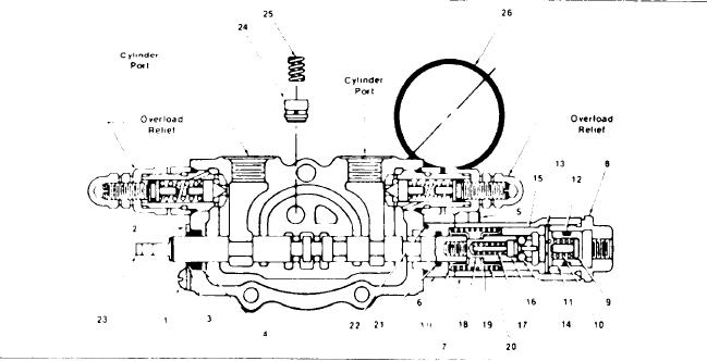
PILOT VALVE PLUNGER SECTION
Install O-rings (21) in cap spacer (6) and slide
INSPECTION
over plunger. Place tang end of plunger in a vise.
Assemble one spring seat (19) over plunger end.
Clean all parts including housing in solvent and
Install plunger spring (20) second spring seat (19)
dry with compressed air. Inspect seal counter
and thread detent pin (18) in the plunger. Slight
bores, they must be free of nicks and contamina-
pressure will be required to compress the plunger
tion. Examine all springs for breaks or distortion.
spring.
Inspect sliding surfaces of piston (11) and pilot
Apply grease to cross holes of detent pin (18) to
plug (8) for nicks, scores or excessive wear. With
hold balls (14) in place. Insert detent spring (17) in
O-ring (12) removed insert piston (11) in the pilot
cam (16).
plug (8) and test for fit. Piston (11) must fit freely
Slide detent sleeve (15) into plunger cap (7) and
w i t h o u t binding through a complete revolution.
place as an assembly over a drive pin or punch.
I n s p e c t O-ring grooves in piston (11) and cap
U s i n g this punch or drive pin depress cam (16)
spacer (6). These surfaces must be free from nicks
w i t h detent spring (17) and insert balls (14) into
and contamination. Examine all O-rings for dam-
detent pin (18) cross holes. Guide detent sleeve
age or deterioration. Any parts found to be defec-
(15) and plunger cap (7) as an assembly over the
tive must be replaced.
detent pin (18). Continue to insert detent sleeve
Examine face of load check poppet (24) and cor-
(15) until it contacts spring seat (19).
r e s p o n d i n g seat in plunger section housing for
Assemble O-ring (12) pin (9) spring (10) and in-
nicks or scratches. If minor scratches are present
sert as an assembly into pilot plug (8). Install spac-
the poppet should be lapped to seat properly. Use
er (13) in plunger cap (7) and thread pilot plug (8)
fine lapping compound and exercise extreme care
assembly into plunger cap (7).
to prevent lapping compound from entering or re-
maining in the valve. Check valve poppet (24) must
Assemble O-ring (4), wiper (3), seal plate (2) and
fit loosely in housing.
secure with machine screws (1). Insert load check
p o p p e t (24) and corresponding spring (25) be-
Test plunger (23) for fit in its respective bore.
tween sections along with O-ring seal (26).
The plunger must be free of score marks and must
fit snugly without binding through a complete revo-
S t a c k inlet, plunger and end cap sections to-
lution.
gether. Be sure O-ring seals (26) between sections
Inspect service port relief seats in section hous-
are properly positioned.
ing. They must be free of nicks or grooves.
Install three tie rods and tighten nuts. A torque
wrench should then be used to apply 14 ft. lb. (1,94
ASSEMBLY
kg. mtrs.) to the two 5/16" (7,9 mm) diameter tie rods
Coat
all parts including housing bores with hy-
and 33 ft. lb. (4.56 kg. mtrs.) to the one 3/8" (9,5 mm)
draulic
oil. Begin reassembly of the valve with
diameter tie rod. Install sectional control valve as-
plunger
sections. Since the internal parts are simi-
sembly on machine and reassemble associated
lar, the
assembly procedure pertains to both.
plumbing.
[ 36 ]

