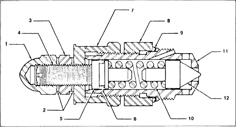
OVERLOAD RELIEF VALVE
be sharp and free from any nicks or grooves. Ex-
GENERAL INFORMATION
amine the O-rings (6 & 9) for indications of damage
or deterioration. Inspect the spring (10) and replace
The Cartridge Relief Valve is a poppet type. Pres-
if found to be broken or distorted. Any parts found
s u r e is set by means of an external adjustment
to be defective must be replaced.
screw. Relief valve failure is usually the result of
foreign particles lodging between the poppet and
p o p p e t seat. To perform service, clean the sur-
rounding area and remove the complete relief valve
ASSEMBLY
cartridge from the main valve housing. Provide a
clean area for relief valve parts.
Coat all parts with hydraulic oil. Assemble O-ring
(9) to sleeve (11) and O-ring (6) to spring guide (5).
Insert poppet (12), spring (10) and spring guide (5)
into sleeve (11). Thread cap (7) onto sleeve (11).
DISASSEMBLY
Install adjusting screw (4), washers (2) locknut (3)
With the relief cartridge removed from the pilot
and cap (1). Tighten the adjusting screw only 1
valve, remove cap (1), locknut (3), washers (2) and
revolution after it contacts the spring. Adjust the
adjust screw (4). Remove cap (7) from sleeve (11).
cartridge relief pressure according to the procedure
Remove spring guide (5), O-ring (6), spring (10),
specified on page A-21-16 of this manual. Prior to
poppet (12) and O-ring (9).
installation, the nut (8) should be backed off one
complete turn. The relief valve is then installed as
INSPECTION
a n assembly into plunger section. It should be
tightened until the face of sleeve (11) is in firm
C l e a n all parts in solvent and dry with com-
c o n t a c t with corresponding housing seat. Apply
pressed air. Examine poppet face (12) for nicks or
25 ft. lb. (3,4564 kg. mtrs.) of torque to cap (7).
s c r a t c h e s . Inspect poppets' corresponding seating
Torque locknut (8) to 10 ft. lb. (1,3825 kg. mtrs.).
surface located in the sleeve (11). This seat must
[35]

