TM 5-3805-258-24-1
P O W E R T R A IN
T R A N S M I S S I O N
FOURTH SPEED REVERSE
S Y S T E M S O P E R A T I O N
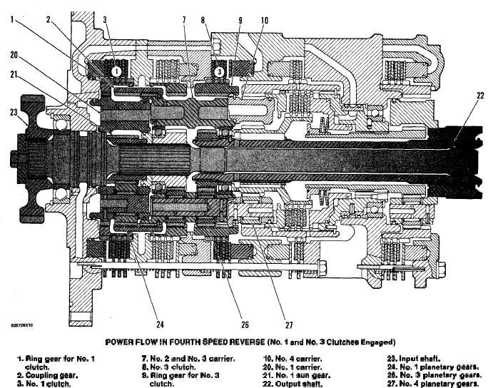
POWER FLOW IN FOURTH SPEED REVERSE (No. 1 and No. 3 Clutches Engaged)
I. Ring gear for No. 1
7. No. 2 and No. 3 carrier.
clutch.
8. ~0. 3 clutch.
2. Ooupling gear.
9. Ring gear for No. 3
3. No. 1 clutch.
clutch.
When the transmission is in FOURTH SPEED
REVERSE, No. 1 and No. 3 clutches are engaged.
The No. 1 clutch holds ring gear (1) for the No. 1
clutch stationary. The No. 3 clutch holds ring gear
(9) for the No. 3 clutch stationary. Input shaft (23)
turns No. 1 sun gear (21). No. 1 sun gear turns No. 1
planetary gear (24). No. 1 carrier (20) is in direct
mechanical connection with ring gear (1).
Since ring gear (1) is held stationary by the No. 1
clutch, so is No. 1 carrier (20). The movement of No.
1 planetary gears (24) causes coupling gear (2) to
10. No. 4 carrier.
23. Input shaft.
20. No. 1 carrier.
24. No. 1 planetary geara.
21. No. 1 sun gear.
26. No. 3 planetary gears.
22. Output shaft.
27. No. 4 planetary gears.
turn in the opposite direction of input shaft (23).
Coupling gear (2) is in direct mechanical connection
with No. 2 and No. 3 carrier (7).
Since ring gear (9) is held stationary by the No. 3
clutch, the movement of No. 2 and No. 3 carrier (7)
causes No. 3 planetary gears (26) to move around the
inside of the ring gear. The No. 3 planetary gears
turn output shaft (22). From the output shaft, power
goes through the output transfer gears to the
differentials.
3-38