TM 5-3805-258-24-1
H Y D R A U L I C
S Y S T E M
S Y S T E M S
O P E R A T I O N
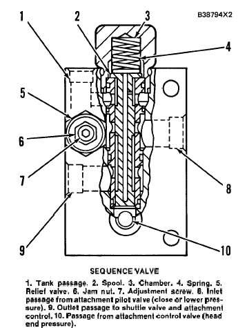
SEQUENCE VALVE
The sequence valve is part of the attachment or
third hydraulic circuit. It is in the implement pilot
system between the attachment pilot valve and the
shuttle valve. The sequence valve permits the tilt
and lift circuits to operate when the attachment
control lever is in CLOSE or LOWER position.
SEQUENCE VALVE
1. Tank passage. 2. Spool. 3. Chamber. 4. Spring. 5.
Relief valve. 6. Jam nut. 7. Adjustment screw. 6. Inlet
passage from attachment pilot valve (close or lower pres-
sure). 9. Outlet passage to shuttle valve and attachment
control. 10. Passage from attachment control valve (head
end pressure).
When the attachment control lever is moved to
CLOSE or LOWER position, pilot oil from the
close or lower stem of the attachment pilot valve
comes into inlet passage (8). Implement pressure
oil from the head end of the attachment cylinders
comes into passage (10). This pressure oil [in pas-
sage (10)], against spool (2), works against spring
(4) and relief valve (5). When the pressure of the
oil to the head end of the attachment cylinders gets
to approximately 15500 kPa (2250 psi), relief valve
(5) opens and releases the pressure of the oil in
chamber (3). Spool (2) now moves up and lets pilot
oil from inlet passage (8) go through outlet pas-
sage (9) to the shuttle valve and on to the attach-
ment valve spool. There is now pilot pressure at
both ends of the attachment valve spool. The
springs on the attachment valve spool cause it to
move back to HOLD position. Implement pressure
oil to the attachment cylinders is now stopped.
When the pressure of the oil in passage (10) gets
below approximately 12400 kPa (1800 psi), relief
valve (5) closes, the pressure in chamber (3) in-
creases and spring (4) moves spool (2) down. This
stops the flow of pilot oil from inlet passage (8)
to outlet passage (9). There is now pilot pressure
oil to one end of the attachment valve spool and
the spool moves back to CLOSE or LOWER posi-
tion. Implement pressure oil again goes to the at-
tachment cylinders.
To change the setting of relief valve (5), loosen
jam nut (6) and turn adjustment screw (7) clock-
wise for an increase in pressure and counterclock-
wise for a decrease in pressure.
3-101